EXCEL 500/600 - INSTALLATION INSTRUCTIONS
EN1R-1047GE51 R0913 22
Table 7. Accuracy of analog input sensors
range
measurement error (without
sensor tolerance)
PT1000 NTC 20K
-58...-4 °F (-50...-20 °C) ≤ 1.2 K ≤ 5.0 K
-4...+32 °F (-20...0 °C) ≤ 0.7 K ≤ 1.0 K
+32...86 °F (0...30 °C) ≤ 0.5 K ≤ 0.3 K
86...158 °F (30...70 °C) ≤ 0.7 K ≤ 0.5 K
158...212 °F (70...100 °C) ≤ 1.2 K ≤ 1.0 K
212...266 °F (100...130 °C) ≤ 1.2 K ≤ 3.0 K
266...302 °F (130...150 °C) ≤ 1.2 K ≤ 5.5 K
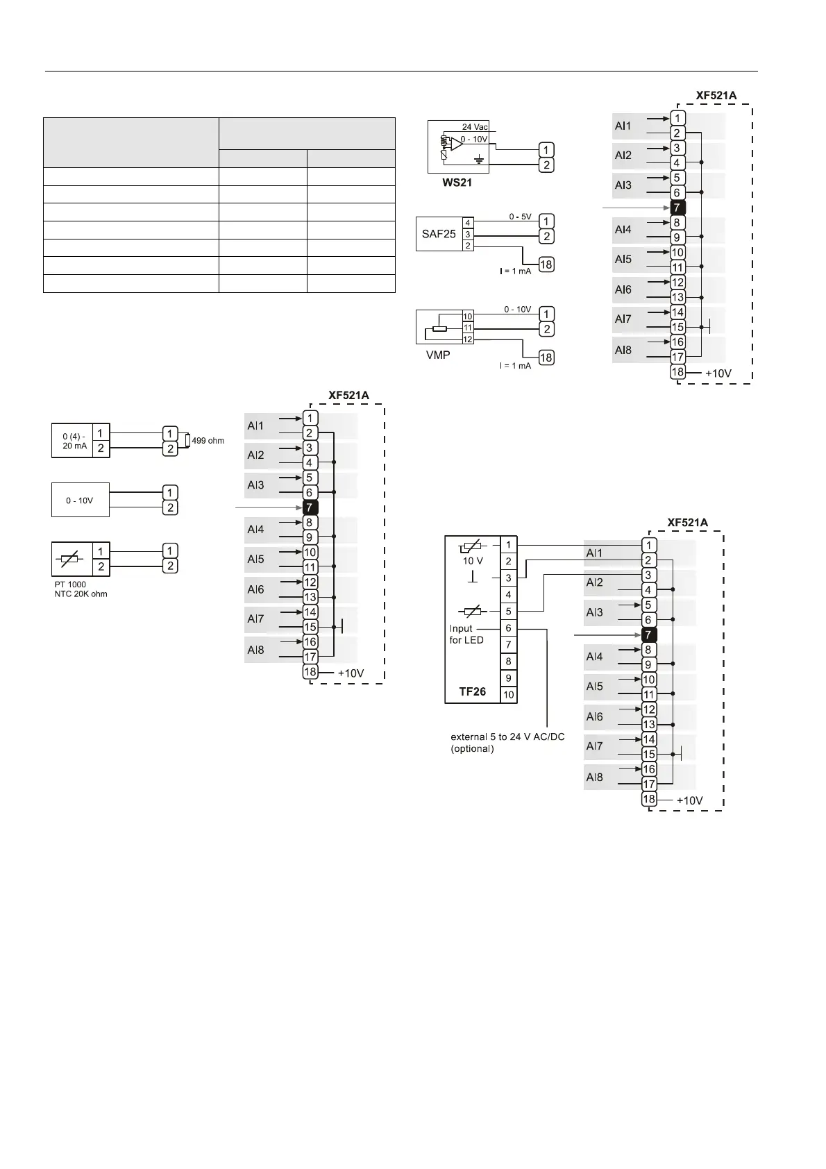
With current sensors, a terminating resistor of R1 = 499 Ω
0.25% must be connected.
Terminal 18 is an auxiliary output voltage (+10 Vdc, I
max
=
5 mA) available for various sensor circuits.
Fig. 50. XF521A Analog Input module connections
Fig. 51 shows several connection examples for various
sensors: WS21 Wind Sensor; SAF 25 Solar Sensor; and VMP
Feedback Potentiometer.
Fig. 51. XF521A connection examples
Fig. 52 shows connections to a TF26.
Terminals 1, 3: temperature adjustment
Terminals 5, 3: room sensor
Terminals 6, 3: LED
Fig. 52. XF521A and TF26 example
XF526 Analog Input Module
Technical Specifications
Number:
eight inputs (AI1 – AI8)
Input:
0...10 Vdc (low-input impedance, 25 kΩ to 10 V /
200 kΩ to GND);
0...20 mA (via external 500-Ω resistor);
4...20 mA (via external 500-Ω resistor);
NTC 20 kΩ (-50...+150 °C);
 Loading...