EXCEL 500/600 - INSTALLATION INSTRUCTIONS
33 EN1R-1047GE51 R0913
NOTE: When changing the baud rate of bus devices, proper
communication cannot be ensured until all bus
devices are set to the same baud rate again.
NOTE: When adding or removing a controller to/from the C-
Bus, it may take up to two minutes to re-initialize the
bus. During this time, communication on the C-bus is
lost.
System Bus Cable Specification
The max. cable length is 4000 ft (1200 m). There are regional
differences as to whether shielded or unshielded cable
must/can be used.
IMPORTANT
In Europe, only shielded cable is permitted, while in
the US, shielded or unshielded cable can be used.
Inside the cabinet:
J-Y-(ST)Y 2 x 2 x 0.8
Outside the cabinet:
A-Y-(ST) 2 x 2 x 0.8
In principle, data transmitting cables should be shielded in
case of RFI.
The following summarizes cable types and gives selection
guidance. Note that baud rate and max. bus length are
related to each other.
Table 25. C-Bus cable types
cable type description recommended for
J-Y-(ST)Y
2 x 2 x 0.8
shielded,
twisted pair
Europe
Inside cabinet
A-Y-(ST)Y
2 x 2 x 0.8
shielded,
twisted pair
Europe
Outside cabinet
AK 3702
unshielded,
twisted pair
US
not approved for Europe
AK 3740A shielded
US (low-cost)
not approved for Europe
Belden 9842 twisted pair
Europe
US also possible
Belden 9841 shielded US
AK 3702
unshielded,
twisted pair
US
not approved for Europe
AK 3740A shielded
US (low-cost)
not approved for Europe
Each end of the shield on the C-Bus should be connected to
the shield terminal of the respective device. Do not connect it
to the cabinet ground or any other ground points.
C-Bus Termination (XC6010)
The XC6010 CPU module may have either the XD505A or
the XD508 submodules mounted on them for C-Bus
communication. Table 24 provides baud rate information for
selecting the module.
The XD508 submodule is equipped with a DIP switch which
activates (ON position) deactivates (OFF position) a
terminating resistor. Depending on where the controller is
located on the bus the DIP switch settings must be as follows:
Table 26. XD508 DIP switch settings for C-Bus
termination
controller location DIP switch setting
beginning or end of bus ON
middle of bus OFF
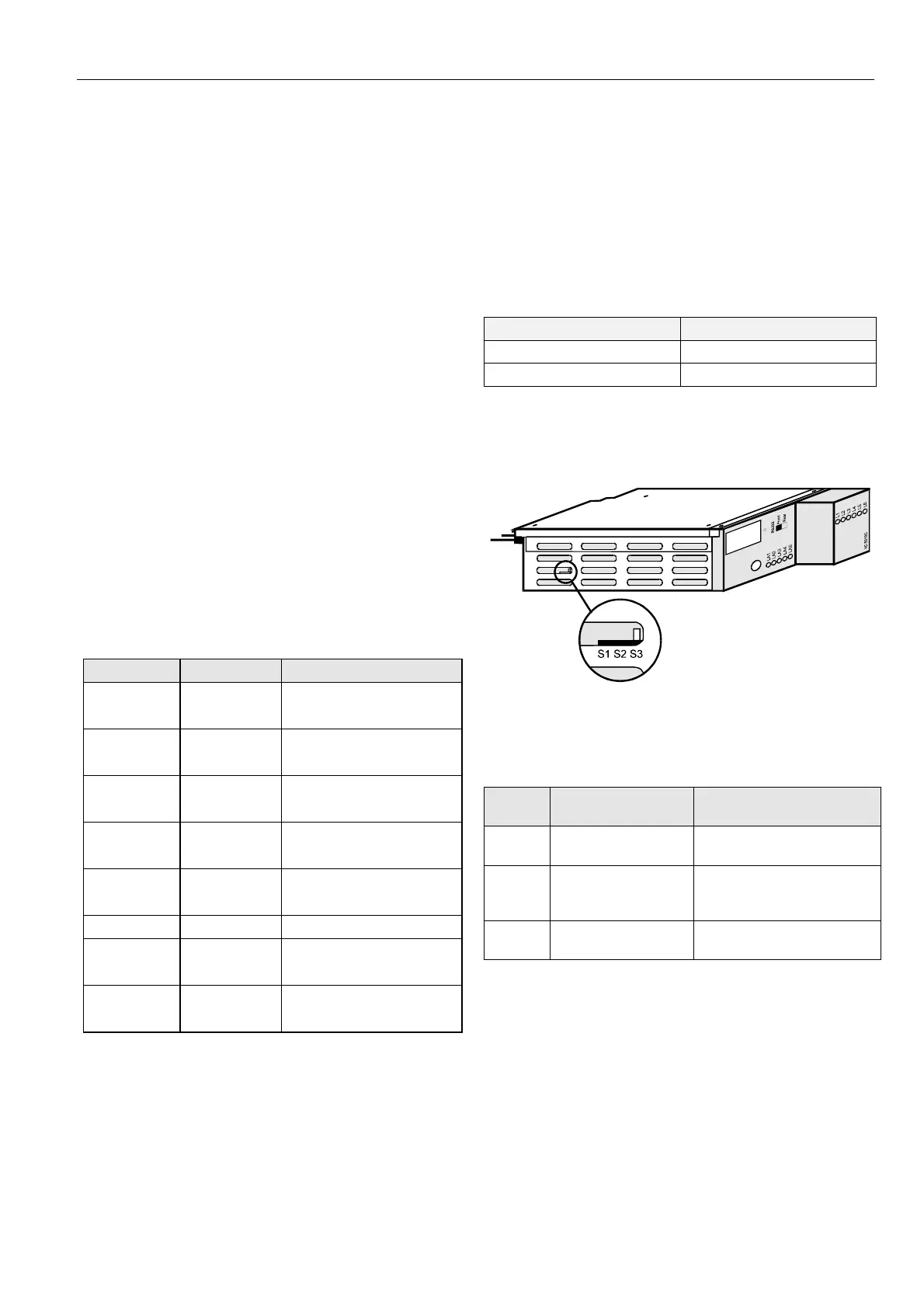
C-Bus Termination (XC5010C)
The XC5010C CPU module contains a switch for setting
different C-Bus baud rates.
Fig. 72. XC5010C C-Bus termination switch location
The bus termination switch for setting the baud rate has three
settings:
Table 27. XC5010C C-Bus termination switch settings
switch
setting
baud rate notes
S1
up to 76800 baud
with bus termination
same functionality as
XD508A, up to 76800 baud
S2
up to 76800 baud
without bus
termination
same functionality as
XD508A, up to 76800 baud
S3 up to 9600 baud
same functionality as
XD505A - Default setting
C-Bus Termination (XCL5010)
The XDL505 application module features a DIP switch for the
C-Bus to set the bus termination appropriate for the
communication speed (see Fig. 69).
 Loading...