EXCEL 500/600 - INSTALLATION INSTRUCTIONS
EN1R-1047GE51 R0913 24
If the inputs are used as totalizers, Table 8 applies.
Table 8. Totalizer inputs specifications
input frequency pulse duration pulse internal chatter time
1, 2 max. 15 Hz min. 20 ms min. 33 ms max. 5 ms
3 to 12 max. 0.4 Hz min. 1.25 s min. 1.25 s max. 50 ms
The inputs shown in row one (Input 1 to 2) may be used as fast totalizers. In this case, the input signal characteristics of row one
are valid. If they are not used as fast totalizers, the values of row two (Inputs 3 to 12) apply to them as well.
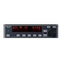
XF522A and XF527 Analog Output Modules
Technical Specifications
Number:
eight analog outputs
Voltage rating:
0…10 V, max. 11 V
Current rating:
max. 1 mA
Resolution:
8 bit
Accuracy:
±150 mV or 1.5% deviation from output voltage
Manual override switches:
XF522A 5 manual override switches (AO1 to AO5)
XF527 No manual override switches
Fig. 56. XF522A and XF527 Analog Output modules
NOTE: The max. output current of 1 mA must not be
exceeded.
NOTE: Both modules are fully pin-compatible.
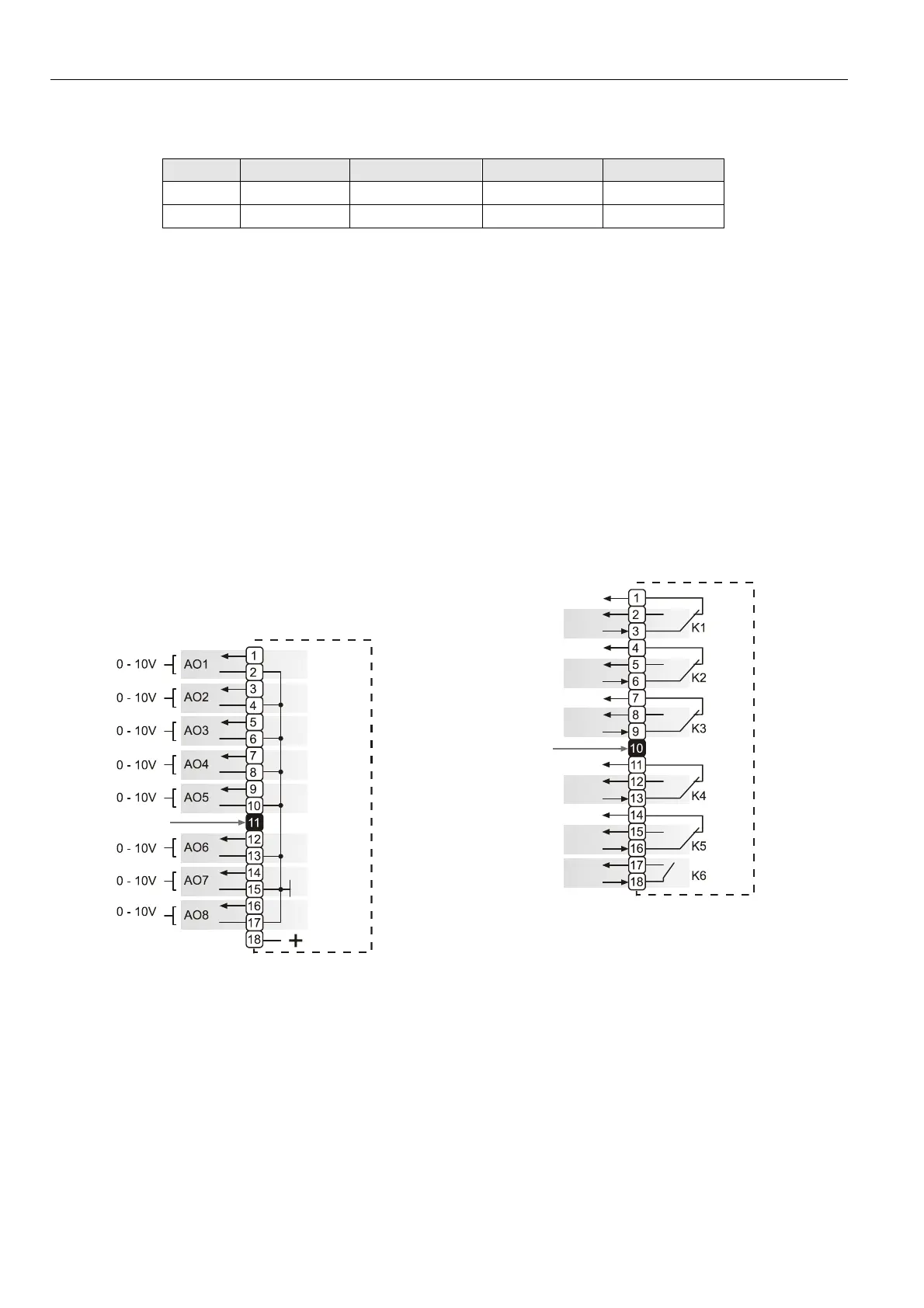
XF524A and XF529 Digital Output Modules
Technical Specifications
Number:
six digital outputs
Voltage rating:
U
MAX
= 240 Vac / I
MAX
= 4 A per output
or
U
MAX
= 30 Vdc / I
MAX
= 4 A per output
Current rating:
max. 12 A per module
Relay contacts:
K1 to K5: changeover contact (voltage-free)
K6: Normally-open contact (voltage-free)
Fig. 57. XF524A and XF529 Digital Output module
NOTE: The max. voltage for U.S. is 24 V.
NOTE: Both modules are fully pin-compatible.
Beginning with V3.04.00 firmware, the online point attribute
normally-open/normally-closed (NO/NC) defines the relation
between the physical input signal and its logical status. See
Table 9.
 Loading...