EXCEL 500/600 - INSTALLATION INSTRUCTIONS
31 EN1R-1047GE51 R0913
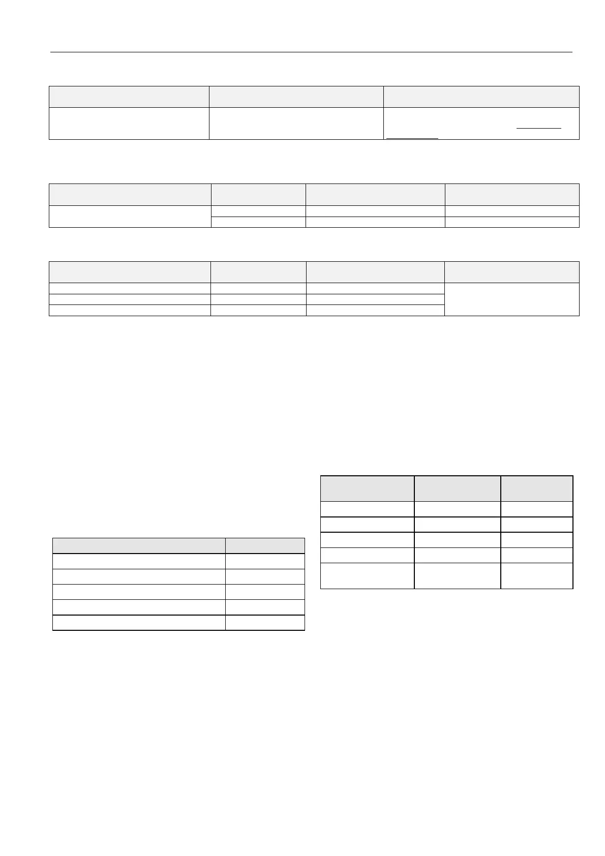
Table 19. Flue Gas Sensors suitable for use with Excel 500/600 (external transducer required)
sensor type
characteristic in cont
olle
(set using CARE)
additional remarks
AGF1 0...10 V = 0…400 °C
requires LC-MV-1xPT1000.0-400°C: converts
PT1000 to 0…10 V: order from: www.rinck-
electronic.de
Table 20. Differential (+ Static Duct) Pressure Sensor suitable for use with Excel 500/600 (no external transducer
required)
sensor type range
characteristic in controlle
(set using CARE)
additional remarks
DPT500 Differential (+ Static Duct)
Pressure Sensor
0...500 Pa 0..10 V = 0...500 Pa set jumper to 0...500 Pa
0... 1000 Pa 0..10 V = 0...1000 Pa set jumper to 0...1000 Pa
Table 21. Differential Pipe Pressure Sensors suitable for use with Excel 500/600 (external transducer not required)
sensor type range
characteristic in controlle
(set using CARE)
additional remarks
FHBN 3+ED1 0 – 2.5 bar 0...10 V = 0...250 kPa
ED1 is an integrated transducer
with 0…10 V output
FHBN 5 +ED1 0 – 5 bar 0...10 V = 0...500 kPa
FHBN 10 +ED1 0 – 10 bar 0...10 V = 0...1000 kPa
COMMUNICATIONS
LONWORKS Bus Wiring
Connection between the Distributed I/O modules and the
CPU are made from the L
ONWORKS connector module
XSL511. The L
ONWORKS bus is a 78-kilobit serial link that
uses transformer isolation so that the bus wiring does not
have a polarity; that is, it is not important which of the two
L
ONWORKS bus terminals are connected to each wire of the
twisted pair.
The LONWORKS bus can be wired in daisy chain, star, loop or
any combination thereof as long as the max. wire length
requirements given below are met. The recommended
configuration is a daisy chain with two bus terminations. This
layout allows for max. LONWORKS bus length, and its simple
structure presents the least number of possible problems,
particularly when adding on to an existing bus.
Table 22. Doubly-terminated bus specifications
cable type max. bus length
Belden 85102 2700 m (8900 ft)
Belden 8471 2700 m (8900 ft)
Level IV, 22 AWG 1400 m (4600 ft)
JY (St) Y 2x2x0.8 900 m (3000 ft)
TIA568A Cat. 5 24AWG, twisted pair 900 m (3000 ft)
NOTES: The cable types listed above are as recommended
by Echelon in their FTT-10A User Guide. The cable
recommended by Honeywell is the level IV, 22
AWG, solid core, nonshielded cable. Belden part
numbers are 9H2201504 (plenum) and 9D220150
(non-plenum).
IMPORTANT
It is recommended that ferrules not be used to
terminate stranded wires inserted in the Distributed
I/O Terminal blocks spring-clamp terminals.
The FTT specification includes two components that must be
met for proper system operation. The distance from each
transceiver to all other transceivers and to the termination
must not exceed the max. node-to-node distance. If multiple
paths exists, the max. total wire length is the total amount of
wire used.
Table 23. Free topology (singly-terminated) specifications
cable type
max. node-to-
node distance
max. total wire
length
Belden 85102 1650 ft (500 m) 1650 ft (500 m)
Belden 8471 1300 ft (400 m) 1650 ft (500 m)
Level IV, 22AWG 1300 ft (400 m) 1650 ft (500 m)
JY (St) Y 2x2x0.8 1050 ft (320 m) 1650 ft (500 m)
TIA568A Cat. 5
24AWG, twisted pair
825 ft (250 m) 1500 ft (450 m)
IMPORTANT
Do not use different wire types or gauges on the
same L
ONWORKS network segment. The step
change in line impedance characteristics would
cause unpredictable reflections on the bus.
NOTE: In the event that the limit on the total wire length is
exceeded, then FTT physical layer repeaters
(FTT 10A) can be added to interconnect segments
and increase the overall length by an amount equal
to the original specification for that cable type and
bus type for each repeater used. For example,
adding repeaters for a doubly-terminated bus using
JY (St) Y 2x2x0.8 cable increases the max. length
3000 ft (900 m) for each repeater.
 Loading...