EXCEL 500/600 - INSTALLATION INSTRUCTIONS
27 EN1R-1047GE51 R0913
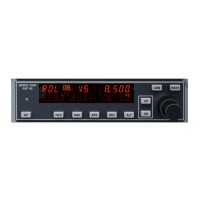
Fig. 64. AC/DC current graphs
1450 Series
All transformers of the 1450 series are designed for 50/60 Hz
AC and have insulated accessory outputs. The transformers
include built-in fuses, line transient/surge protection and AC
convenience outlets and meet NEC class 2 requirements.
Table 12. 1450 Series transformers
part #
1450 7287
primary side secondary side
-001 120 Vac 24 Vac, 50 VA
-002 120 Vac
2 x 24 Vac, 40 VA and 100 VA
from separate transformer
-003 120 Vac
24 Vac, 100 VA and 24 Vdc
600 mA
-004 240/220 Vac 24 Vac, 50 VA
-005 240/220 Vac
2 x 24 Vac, 40 VA and 100 VA
from separate transformer
-006 240/220 Vac
24 Vac, 100 VA and 24 Vdc
600 mA
Standard Transformers
Standard commercially available transformers must fulfill the
specifications stated in Table 13.
Table 13. Requirements for standard transformers
output voltage impedance AC current
24.5 Vac to 25.5 Vac
1.15 Ω
max. 2 A
24.5 Vac to 25.5 Vac
0.40 Ω
max. 6 A
24.5 Vac to 25.5 Vac
0.17 Ω
max. 12 A
Screw Terminal Block Installation Procedure
WARNING
High Voltage
Risk of death or electrical shock.
— Do not connect line power supply directly to the
terminals.
— Insulate devices with 120 Vac / 230 Vac by a
transformer.
1. Make sure that the power supply of the cabinet is
disconnected.
2. Make sure that the power supply of the cabinet is
disconnected and the application module is plugged in
the housing.
IMPORTANT
When installing a separate external transformer, do
not connect the cabinet ground to the controller
system ground.
3. If the distance between the controller and an actuator or
sensor with 24 Vac supply is greater than 550 ft
(170 m):
a) Choose a transformer from the transformers
listed in section "Power Supply" on page 26.
b) Connect the chosen transformer directly to the
actuator or sensor.
4. Select one of the transformers of the CRT-series or
1450 series from the tables on the previous page or
take a commercially available standard transformer
fulfilling the requirements listed in Table 13.
5. Make sure that the application module is attached to
the controller housing.
IMPORTANT
The transformer feeding the Excel 500 Controller
must be in the same cabinet. For the selection of the
transformer, the max. DC current must be
considered if field devices with DC load are used.
The secondary side of the transformer must not be
connected to earth ground.
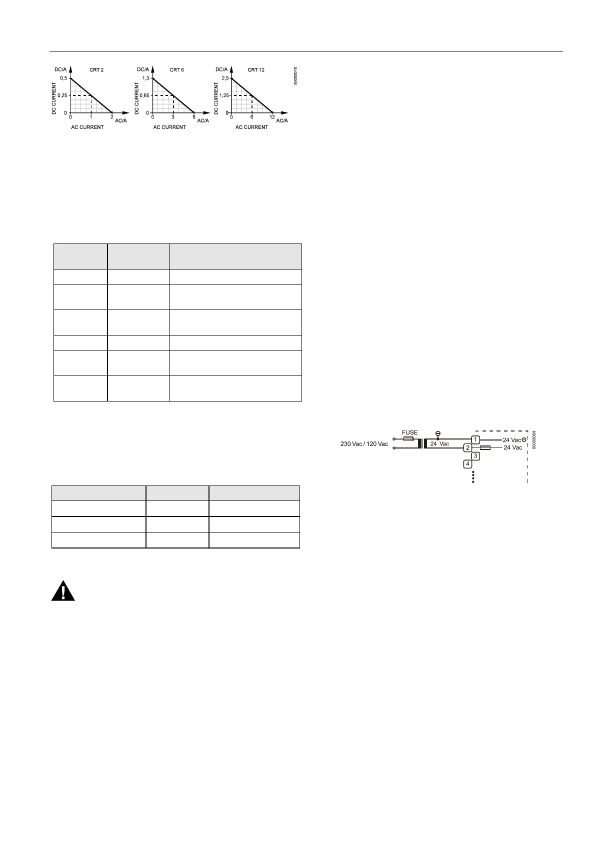
Fig. 65. Connecting the power supply
6. Connect the 24 Vac (-) on the secondary side of the
transformer to terminal 1 on the Screw Terminal Block.
7. Connect the 24 Vac on the secondary side of the
transformer to terminal 2 on Screw Terminal Block.
 Loading...