EXCEL 500/600 - INSTALLATION INSTRUCTIONS
23 EN1R-1047GE51 R0913
PT1000 (-50...+150 °C)
PT1000 (0...+400 °C)
PT100 (-50...+150 °C)
PT3000 (-50...+150 °C)
Balco 500 (-50...+150 °C)
Protection:
up to 40 Vdc / 24 Vac
Resolution:
12-bit resolution
Accuracy:
±75 mV or 0.75% (0...10 V)
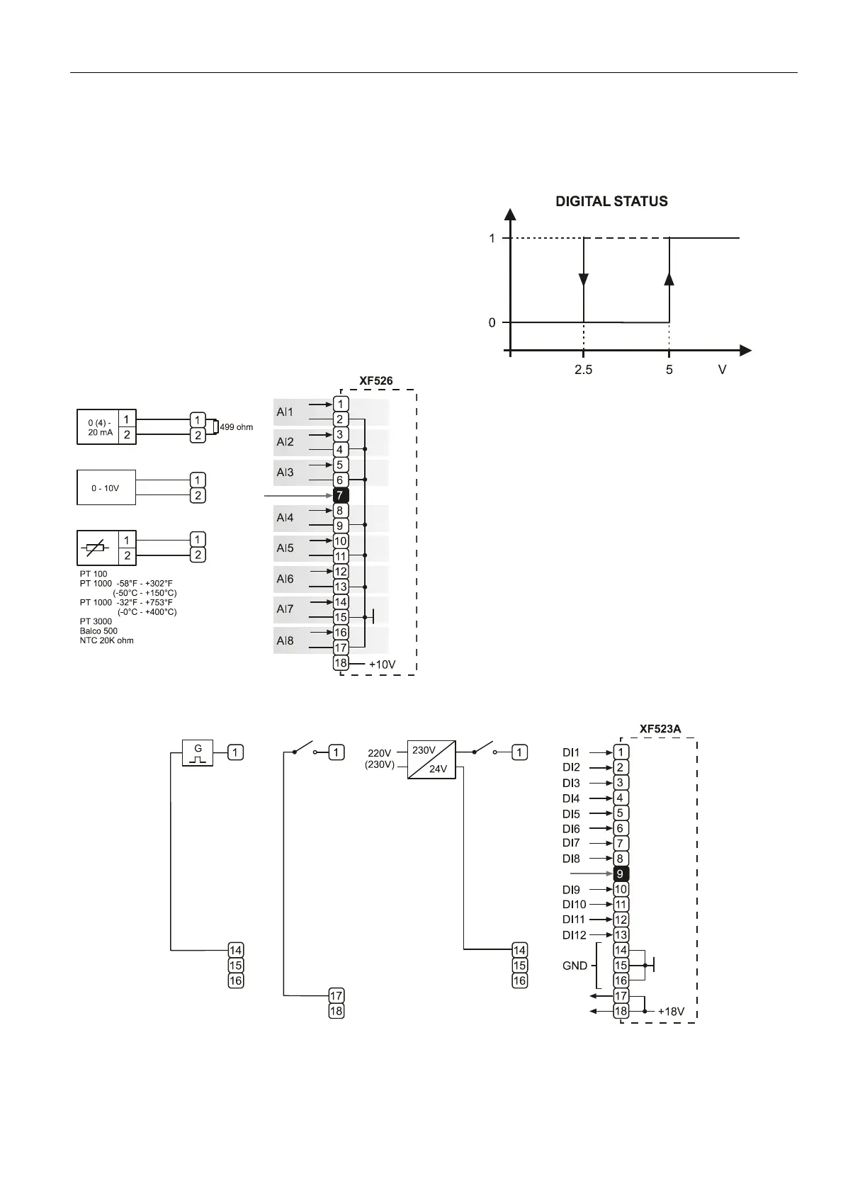
See also Table 7.
With current sensors, a terminating resistor of R1 = 499 Ω
0.25% must be connected.
Terminal 18 is an auxiliary output voltage (+10 Vdc,
I
max
= 5 mA) available for various sensor circuits.
Fig. 53. XF526 Analog Input module connections
XF523A Digital Input Module
The digital input module can process DC or AC voltage
signals. The module has 12 digital inputs. When the input
voltage reaches 5 V, the digital signal is set to a status of "1".
With a hysteresis of 2.5 V, the digital input signal must fall
below 2.5 V before a digital status of "0" is reported.
Fig. 54. Digital input hysteresis
The LED functionality of each digital input channel can be
altered via 12 internal DIP switches. In the ON position
(default), the LED will illuminate when energized (normally-
open contacts). In the OFF position, the LED will illuminate
when de-energized (normally-closed contacts).
Max. signal voltage from non-Honeywell voltage sources:
DC Voltage: V
max
= 40 V
AC Voltage: V
max
= 28 V / 50 Hz
Input resistance:
R
i
= 15 kΩ
Fig. 55. XF523A connection examples
 Loading...