How the Instrument Works
Standard and Enhanced Trigger Modes
Example of gating
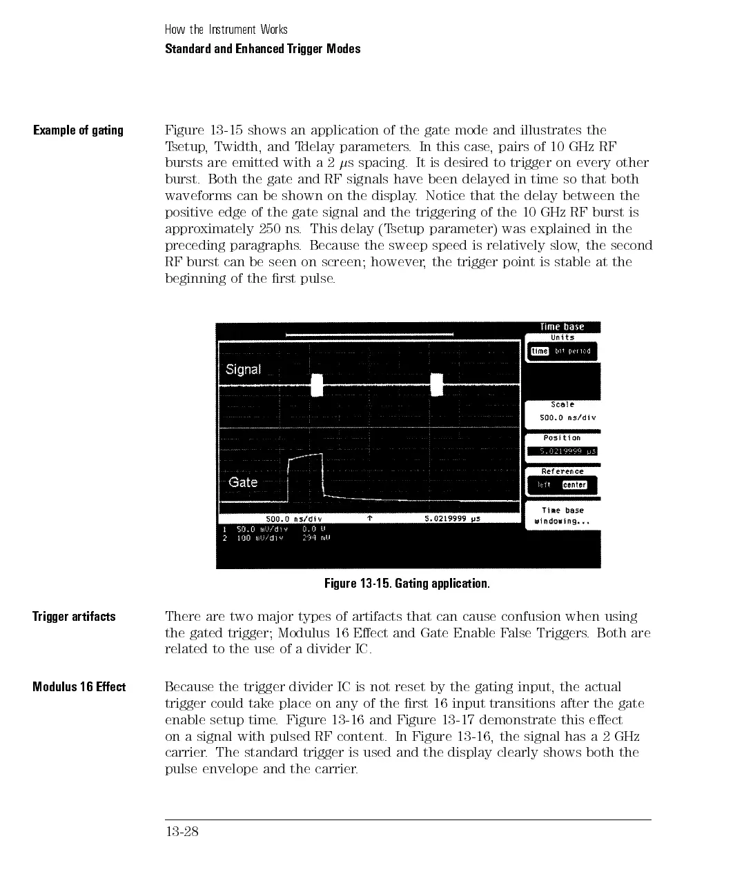
Figure 13-15 shows an application of the gate mode and illustrates the
Tsetup, Twidth, and Tdelay parameters. In this case, pairs of 10 GHz RF
bursts are emitted with a 2
s spacing. It is desired to trigger on every other
burst. Both the gate and RF signals have been delayed in time so that both
waveforms can be shown on the display. Notice that the delay between the
positive edge of the gate signal and the triggering of the 10 GHz RF burst is
approximately 250 ns. This delay (Tsetup parameter) was explained in the
preceding paragraphs. Because the sweep speed is relatively slow, the second
RF burst can be seen on screen; however, the trigger point is stable at the
beginning of the rst pulse.
Figure 13-15. Gating application.
Trigger artifacts
There are two major types of artifacts that can cause confusion when using
the gated trigger; Modulus 16 Eect and Gate Enable False Triggers. Both are
related to the use of a divider IC.
Modulus
16
Eect
Because
the
trigger
divider
IC
is not
reset
by
the
gating
input,
the
actual
trigger could take place
on any of the rst 16 input transitions after the gate
enable setup time
. Figure
13-16 and Figure 13-17 demonstrate this eect
on a signal with pulsed RF content.
In Figure 13-16, the signal has a 2 GHz
carrier. The standard trigger is used and the display clearly shows both the
pulse
envelope and the carrier
.
13-28