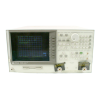
Assembly
Replacement Sequence
The follo
wing steps
sho
w
the
sequence
to
replace
an
assem
bly
in
an
HP 8753D
Netw
ork
Analyzer.
1.
Identify
the fault
y group.
Refer to
Chapter 4,
\Start
T
roublesho
oting
Here."
F
ollo
w
up
with
the
appropriate
troublesho
oting
c
hapter
that
iden
ties
the
fault
y
assem
bly
.
2.
Order
a
replacemen
t
assem
bly
.
Refer to
Chapter 13,
\Replaceable P
arts."
3.
Replace the
faulty
assembly
and
determine
what
adjustmen
ts
are
necessary
.
Refer
to
Chapter
14,
\Assem
bly
Replacemen
t
and
P
ost-Repair
Pro
cedures."
4.
P
erform the
necessary adjustmen
ts. Refer
to Chapter
3,
\Adjustmen
ts
and
Correction
Constan
ts."
5.
P
erform
the
necessary
p
erformance
tests.
Refer
to
Chapter
2, \System
Verication
and
P
erformance
Tests."
Receiver
F
ailure
Error
Messages
The
error
messages whic
h indicate
receiv
er
group
problems
ma
y
b
e
caused
b
y
the
instrumen
t
itself
or
b
y
external
devices
or
connections.
Remem
ber
that RF
OUT
m
ust
b
e
connected
to
input
R
to
main
tain
phase
lo
c
k
(unless
in
ternal
cables
are
mo
v
ed). The
following
three
error
messages
share
the
same
description.
CAUTION: OVERLOAD
ON
INPUT
A,
POWER
REDUCED
CAUTION:
OVERLOAD
ON
INPUT
B,
POWER
REDUCED
CAUTION:
OVERLOAD
ON
INPUT
R,
POWER
REDUCED
If
an
y
of
the
ab
o
v
e
error
messages
app
ear,
you
hav
e
exceeded
appro
ximately
+3
dBm
at
one
of
the
input
p
orts.
The
RF
output
p
o
w
er
is
automatically
turned
o.
The
annotation
P
app
ears in
the left
margin of
the
displa
y
to
indicate
that
the
p
o
w
er
trip
function
has
b
een
activ
ated.
T
o
reset
the
analyzer's
po
wer
and regain
con
trol
of
the
p
o
w
er
lev
el,
do
the
follo
wing:
1. Remo
ve
any
devices
under
test
whic
h
ma
y
ha
v
e
con
tributed
excess
p
o
w
er
to the
input.
2.
Connect
the equipmen
t
as
sho
wn
in
Figure
8-1
.
3.
Press
4
MENU
5
NNNNNNNNNNNNNNN
NN
POWER
4
0
54
2
1
5
NNNNNNNNNNNNNNN
NNNNNNNNNNNNNNNNNNNNNNNNN
NNNN
POWER TRIP OFF
to return the p o
wer lev
el to the preset state.
If the p o
wer trip indicator (P) do es not reapp ear, recongure the test
setup to k
eep input
po
wer lev
els at
0 dBm or b elo
w.
If P reapp ears, con
tinue with \Chec
k the R, A, and B inputs."
8-2 Receiver Troubleshooting DRAFT
3/21/106 15:13
Artisan Scientific - Quality Instrumentation ... Guaranteed | (888) 88-SOURCE | www.artisan-scientific.com

 Loading...