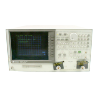
The HP
85046A/B and
HP 85047A
S-parameter test
sets con
tain
the
hardw
are
required
to
mak
e
sim
ultaneous
transmission
and
reection
measuremen
ts
in
b
oth
the forw
ard and
reverse
directions.
An
RF
path switc
hin
the test
set allo
ws rev
erse measuremen
ts to
b
e
made
without
changing
the connections
to
the
device
under
test.
T
est Set
Step A
ttenuator
The 70
dB step
attenuator
contained
in
the
test
set
is
used
to
adjust
the
p
o
w
er
lev
el
to
the
DUT
without
c
hanging
the
lev
el
of
the
inciden
t
p
o
w
er
in
the reference
path. The
attenuator
in
the
HP
85046A/B
or
HP
85047A
test set
is con
trolled from
the fron
t
panel
of
the
analyzer
using
the
N
N
N
NN
NN
NN
NN
N
N
N
N
N
N
N
N
N
N
N
N
N
N
N
N
N
NN
NN
NN
NN
N
N
N
N
N
N
N
N
N
N
N
N
N
N
N
N
N
ATTENUATOR
PORT 1
or
N
N
N
NN
NN
NN
NN
N
N
N
N
N
N
N
N
N
N
N
N
N
N
N
N
N
NN
NN
NN
NN
N
N
N
N
N
N
N
N
N
N
N
N
N
N
N
N
N
ATTENUATOR
PORT 2
softkeys
lo
cated
in
the
p
o
w
er
men
u.
The
Receiv
er
Block
The
receiv
er
blo
c
k
con
tains
three
sampler/mixers
for
the
R, A,
and B
inputs.
The
signals
are
sampled,
and
do
wn-conv
erted to
pro duce
a
4
kHz
IF
(in
termediate
frequency).
A
m
ultiplexer
sequen
tially
directs
eac
h
of
the
three
IF
signals
to
the
ADC
(analog
to
digital
con
v
erter)
where
it
is
con
v
erted
from
an
analog
to
a
digital
signal
to
b
e
measured
and pro
cessed
for
viewing
on
the
displa
y
.
Both
amplitude
and
phase
information
are
measured
sim
ultaneously
,
regardless
of
what is
display
ed on
the analyzer.
The
Microprocessor
A
micropro
cessor
tak
es
the
ra
w
data and
performs
all
the
required
error
correction,
trace
math,
formatting,
scaling,
a
v
eraging,
and
mark
er
op
erations,
according
to
the
instructions
from
the
fron
t
panel
or
o
v
er
HP-IB.
The
formatted
data
is
then
displa
y
ed.
Required
P
eripheral
Equipment
In
addition
to
the
analyzer
and
the
test
set,
a
system
requires
calibration
standards
for v
ector
accuracy
enhancemen
t,
and
cables
for
in
terconnections.
A
Close
Look
at
the
Analyzer's
Functional
Groups
The
op
eration
of
the
analyzer
is
most
logically
describ
ed
in v
e functional
groups. Eac
h group
consists
of
sev
eral
ma
jor assem
blies,
and
p
erforms
a
distinct
function
in
the
instrumen
t. Some
assemblies are related to more than one group, and in fact all the groups are to some exten
t
interrelated and aect eac
h other's p erformance.
Power Supply
.
The po
wer supply functional
group consists of the A8 p ost regulator and the
A15 preregulator.
It supplies p o
wer to the other assem
blies in the instrumen
t.
Digital Con
trol.
The digital con
trol group consists of the A1 fron
t panel and A2 fron
t
panel pro cessor, the A9 CPU, the
A16 rear panel, the A18 displa
y and the A19 graphics
system pro cessor (GSP). The A10 digital IF assembly is also related to this group. These
assemblies combine to provide digital control for the analyzer and an HP 85047A or
85046A/B S-parameter test set if used.
Source.
The source group consists of the A3 source, A7 pulse generator, A11 phase lo ck,
A12 reference, A13 fractional-N (analog), and A14 fractional-N (digital) assemblies. The A4
DRAFT
3/21/106 15:14
Theory of Operation 12-3
Artisan Scientific - Quality Instrumentation ... Guaranteed | (888) 88-SOURCE | www.artisan-scientific.com

 Loading...