Source
Super Lo
w Band
Operation
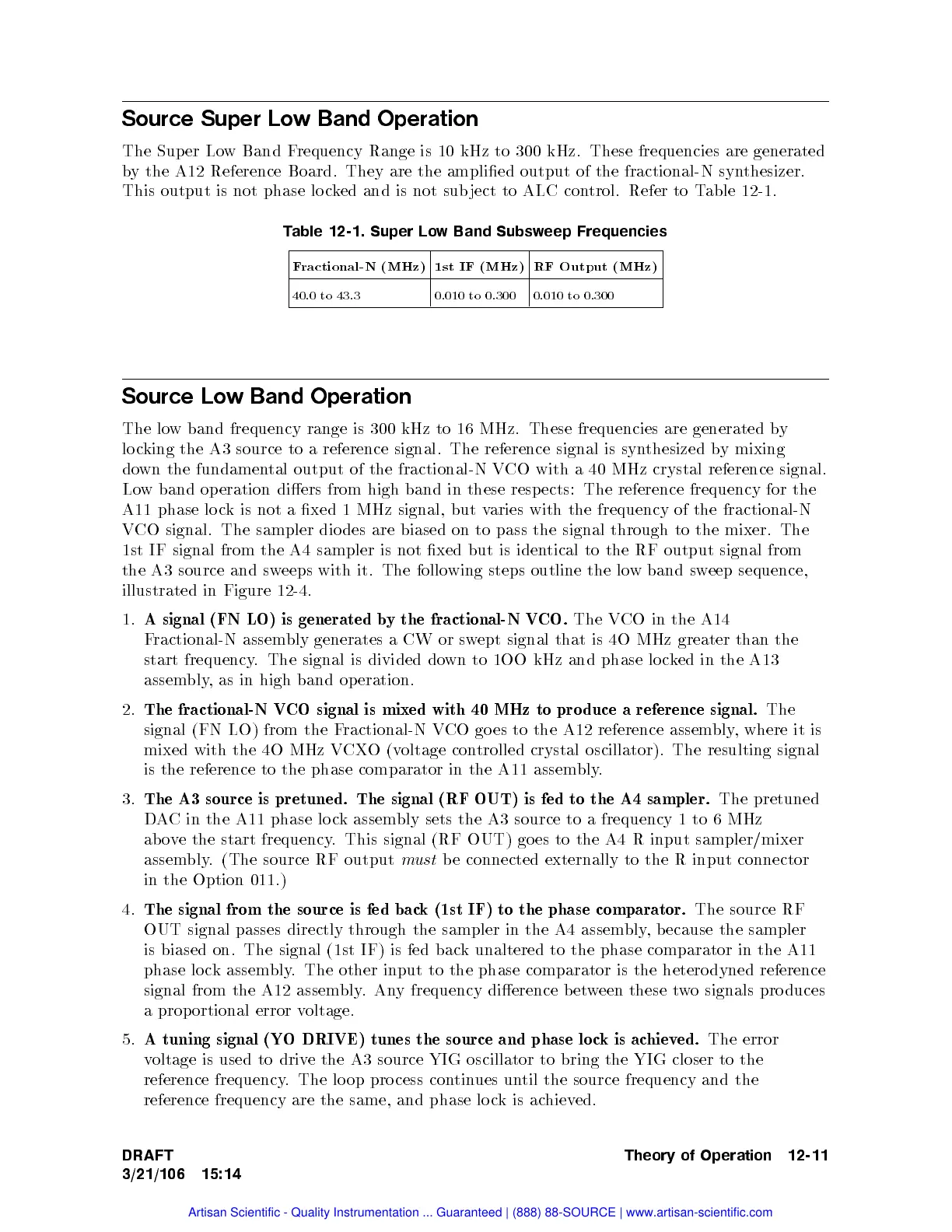
The Sup
er Lo
w
Band
F
requency
Range
is
10
kHz
to
300
kHz.
These frequencies
are generated
b
y
the
A12
Reference
Board.
They are
the amplied
output of
the fractional-N
synthesizer.
This
output is
not phase
lo c
ked
and is
not
sub
ject
to
ALC
con
trol.
Refer
to
T
able
12-1.
T
able
12-1.
Super
Lo
w
Band
Subsw
eep Frequencies
F
ractional-N (MHz)
1st
IF (MHz)
RF
Output (MHz)
40.0
to
43.3
0.010
to
0.300
0.010
to
0.300
Source
Lo
wBand
Operation
The
lo
w
band frequency
range is
300
kHz
to
16
MHz.
These
frequencies
are
generated
b
y
lo c
king
the
A3
source
to
a
reference
signal.
The
reference
signal
is
syn
thesized
b
y
mixing
do
wn
the
fundamen
tal
output
of
the
fractional-N
VCO
with a
40 MHz
crystal
reference
signal.
Lo
w
band
op
eration
diers
from
high
band
in
these
resp
ects:
The
reference
frequency
for the
A11 phase
lo c
kis
not
a
xed
1
MHz
signal,
but
v
aries
with
the
frequency
of
the
fractional-N
V
CO
signal.
The
sampler
dio
des
are biased
on to
pass
the
signal
through
to
the
mixer.
The
1st
IF
signal
from
the
A4
sampler
is
not
xed
but
is
iden
tical
to the
RF output
signal
from
the
A3
source
and
sw
eeps
with
it.
The
follo
wing
steps
outline
the
lo
w
band
sw
eep
sequence,
illustrated
in
Figure
12-4
.
1.
A
signal
(FN
LO)
is
generated
b
y
the
fractional-N
V
CO.
The V
CO
in
the
A14
F
ractional-N
assem
bly
generates
a
CW
or
sw
ept
signal
that
is
4O
MHz
greater
than
the
start
frequency
.
The signal
is
divided
do
wn
to
1OO
kHz
and
phase
lo
c
k
ed
in
the
A13
assem
bly
,
as
in
high
band
op
eration.
2.
The
fractional-N
V
CO
signal
is
mixed
with
40 MHz
to pro
duce
a
reference
signal.
The
signal
(FN
LO)
from
the
F
ractional-N
V
CO
go
es
to
the
A12
reference assem
bly,
where it
is
mixed with
the 4O
MHz
V
CX
O
(v
oltage
con
trolled
crystal
oscillator).
The
resulting
signal
is
the
reference
to
the
phase comparator
in the
A11 assem
bly
.
3.
The
A3
source
is
pretuned.
The
signal
(RF
OUT)
is
fed
to the
A4 sampler.
The pretuned
DA
Cin
the A11
phase
lo
c
k
assem
bly
sets
the
A3
source
to
a frequency
1to
6MHz
ab
o
v
e
the
start
frequency
.
This
signal
(RF
OUT) go
es
to
the
A4
R
input
sampler/mixer
assembly. (The source RF output
must
be connected
externally to the R input connector
in
the Option 011.)
4.
The signal from the source is fed bac
k (1st IF) to the phase comparator.
The source RF
OUT signal passes directly through the
sampler in the A4 assem
bly, b ecause the sampler
is biased on. The signal (1st IF) is fed bac
k unaltered to the phase comparator in the A11
phase lo c
k assem
bly. The other input
to the phase comparator is the hetero dyned reference
signal from the A12 assem
bly.An
y frequency dierence b et
ween these t
wo signals pro duces
a prop ortional error voltage.
5.
A tuning signal (YO DRIVE) tunes the source and phase lo ckisachieved.
The error
voltage is used to drive the A3 source YIG oscillator to bring the YIG closer to the
reference frequency. The lo op pro cess continues until the source frequency and the
reference frequency are the same, and phase lo ckisachieved.
DRAFT
3/21/106 15:14
Theory of Operation 12-11
Artisan Scientific - Quality Instrumentation ... Guaranteed | (888) 88-SOURCE | www.artisan-scientific.com

 Loading...


