4.
Press
N
NN
N
N
N
N
N
N
N
N
N
N
N
N
N
NN
NN
NN
NN
NN
NN
N
N
N
N
N
N
N
N
N
N
EXECUTE
TEST
and
N
NN
N
N
N
N
N
N
N
N
YES
at
the
prompt
to
alter
the
correction
constan
ts.
Alternating
v
ertical
bars
of
three
dieren
t
in
tensities will
be
drawn
on the
display
.Eac
h
bar has
an
umb
er written
belo
w it:
0, 1,
or
2.
5.
Adjust the
analyzer fron
t
panel
knob
un
til
the
v
ertical
bar
lab
eled
\1" is
just barely
visible
against
the
blac
k
b
order.
Vertical
bar \0"
must
not b
e visible.
Maximum
Intensity
Adjustment
This
adjustment
ensures that
the ligh
t output
at
the
100%
in
tensit
y
lev
el
is
equal
to,
or
less
than
150
Nits.
The
lev
el
is
set
using
a
photometer
to
measure
the
output
ligh
t.
Caution
If
y
ou
op
erate
the
displa
y
at
in
tensities
higher
than
150
Nits,
y
ou
ma
y reduce
the
life
of
the
displa
y.
6.
Press
the top
softkey
.
The
analyzer
displa
y
should
ha
v
e
an
all
white
screen.
7.
Zero
the
photometer
according
to
the
man
ufacturer's
instructions.
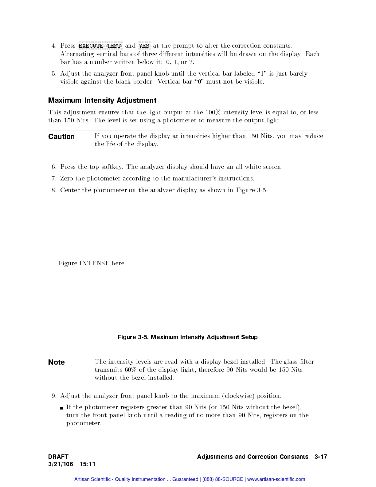
8.
Cen
ter
the
photometer
on
the
analyzer displa
yas
shown
in
Figure
3-5
.
Figure
INTENSE
here.
Figure 3-5. Maximum Intensity Adjustment Setup
Note
The in
tensitylev
els
are read with a displa
y b ezel installed. The glass lter
transmits 60% of the displa
y light, therefore 90 Nits w
ould b e 150 Nits
without the b ezel installed.
9. Adjust the analyzer front panel knob to the maximum (clo ckwise) p osition.
If the photometer registers greater than 90 Nits (or 150 Nits without the b ezel),
turn the front panel knob until a reading of no more than 90 Nits, registers on the
photometer.
DRAFT
3/21/106 15:11
Adjustments and Correction Constants 3-17
Artisan Scientific - Quality Instrumentation ... Guaranteed | (888) 88-SOURCE | www.artisan-scientific.com

 Loading...


