OSPF 124
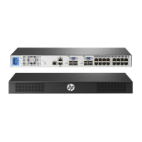
e. Configure the OSPF Interface 2, and attach it to the stub area 1.
f. Click Submit.
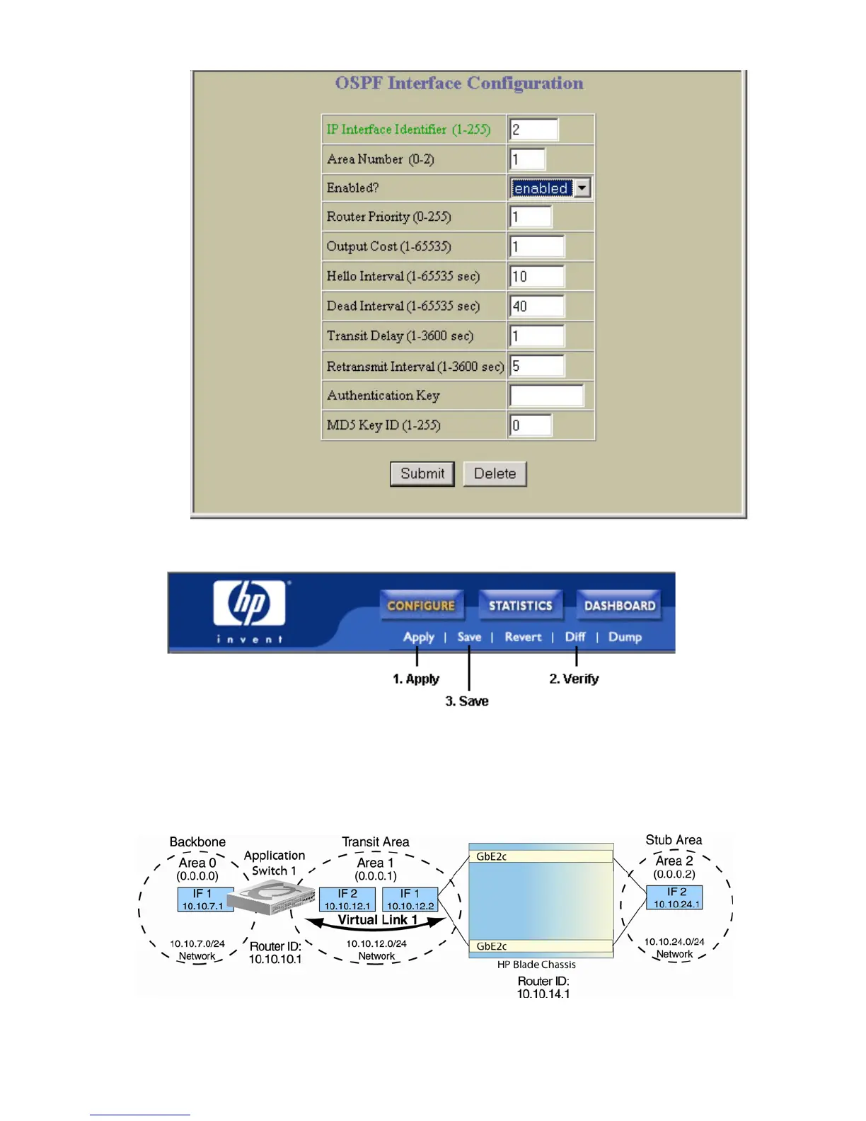
6. Apply, verify, and save the configuration.
Example 2: Virtual links
In the example shown in the following figure, area 2 is not physically connected to the backbone as is usually
required. Instead, area 2 will be connected to the backbone via a virtual link through area 1. The virtual link must be
configured at each endpoint.
Figure 22 Configuring a virtual link
Configuring OSPF for a virtual link on Switch A
1. Configure IP interfaces on each network that will be attached to the switch.
 Loading...