OSPF 127
9. Configure the virtual link.
The nbr router ID configured in this step must be the same as the router ID that was configured for Switch A in
step 2.
>> OSPF Interface 2 # ../virt 1 (Specify a virtual link number)
>> OSPF Virtual Link 1 # aindex 1 (Specify the transit area
for the virtual link)
>> OSPF Virtual Link 1 # nbr 10.10.10.1(Specify the router ID
of the recipient)
>> OSPF Virtual Link 1 # enable (Enable the virtual link)
10. Apply and save the configuration changes.
>> OSPF Interface 2 # apply (Apply all changes)
>> OSPF Interface 2 # save (Save all changes)
Other Virtual Link Options
• You can use redundant paths by configuring multiple virtual links.
• Only the endpoints of the virtual link are configured. The virtual link path may traverse multiple routers in an
area as long as there is a routable path between the endpoints.
Example 3: Summarizing routes
By default, ABRs advertise all the network addresses from one area into another area. Route summarization can be
used for consolidating advertised addresses and reducing the perceived complexity of the network.
If the network IP addresses in an area are assigned to a contiguous subnet range, you can configure the ABR to
advertise a single summary route that includes all the individual IP addresses within the area.
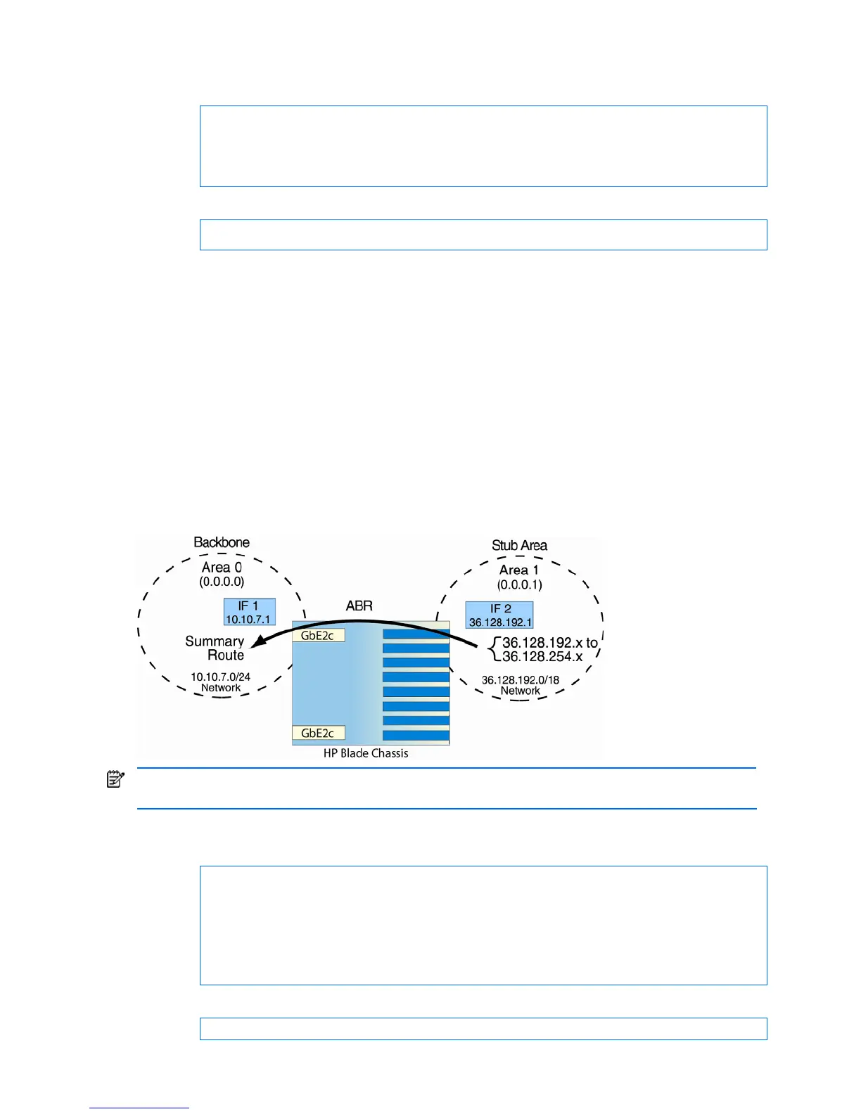
The following example shows one summary route from area 1 (stub area) injected into area 0 (the backbone). The
summary route consists of all IP addresses from 36.128.192.0 through 36.128.254.255 except for the routes in the
range 36.128.200.0 through 36.128.200.255
Figure 23 Summarizing routes
NOTE: You can specify a range of addresses to prevent advertising by using the hide option. In this example,
routes in the range 36.128.200.0 through 36.128.200.255 are kept private.
Follow this procedure to configure OSPF support on Switch A and Switch B, as shown in the figure.
1. Configure IP interfaces for each network which will be attached to OSPF areas.
>> # /cfg/l3/if 1 (Select menu for IP interface 1)
>> IP Interface 1 # addr 10.10.7.1(Set IP address on backbone network)
>> IP Interface 1 # mask 255.255.255.0(Set IP mask on backbone network)
>> IP Interface 1 # ena (Enable IP interface 1)
>> IP Interface 1 # ../if 2(Select menu for IP interface 2)
>> IP Interface 2 # addr 36.128.192.1(Set IP address on stub area
network)
>> IP Interface 2 # mask 255.255.192.0(Set IP mask on stub area network)
>> IP Interface 2 # ena (Enable IP interface 2)
2. Enable OSPF.
>> IP Interface 2 # /cfg/l3/ospf/on
 Loading...