Removal and Replacement Procedures
Power Button/LED Assembly
To remove the power button/LED assembly:
1. Power down and remove power from the server. Refer to “Powering Down the Server” in
this chapter.
2. Unlock and open the front bezel (tower server only).
IMPORTANT: You must unlock the tower bezel before removing the access panel. Refer to “Front
Bezel” in this chapter.
3. Remove the access panel. Refer to “Access Panel” in this chapter.
4. Remove the processor air baffle. Refer to “Processor Air Baffle” in this chapter.
5. Remove the PCI-X expansion boards. Refer to “PCI-X Expansion Boards” in this
chapter.
6. Remove the center wall. Refer to “Center Wall” in this chapter.
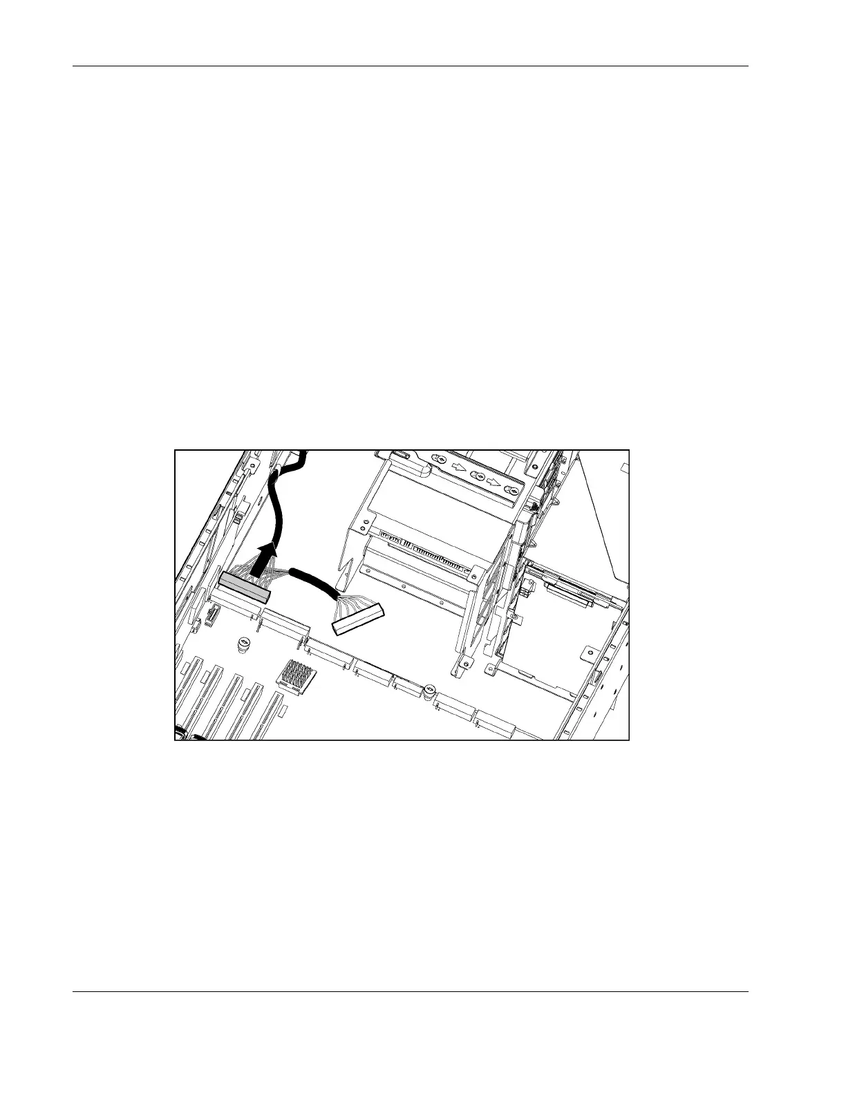
7. Disconnect the power button/LED assembly cable from the system board and the power
supply backplane.
Figure 2-37: Disconnecting the power button/LED assembly cable
8. Release the cable from the clip on the chassis wall.
2-40 HP ProLiant ML370 Generation 3 Server Maintenance and Service Guide
 Loading...