LED Indicators and Switches
Front Panel LEDs
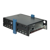
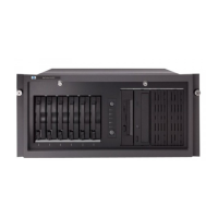
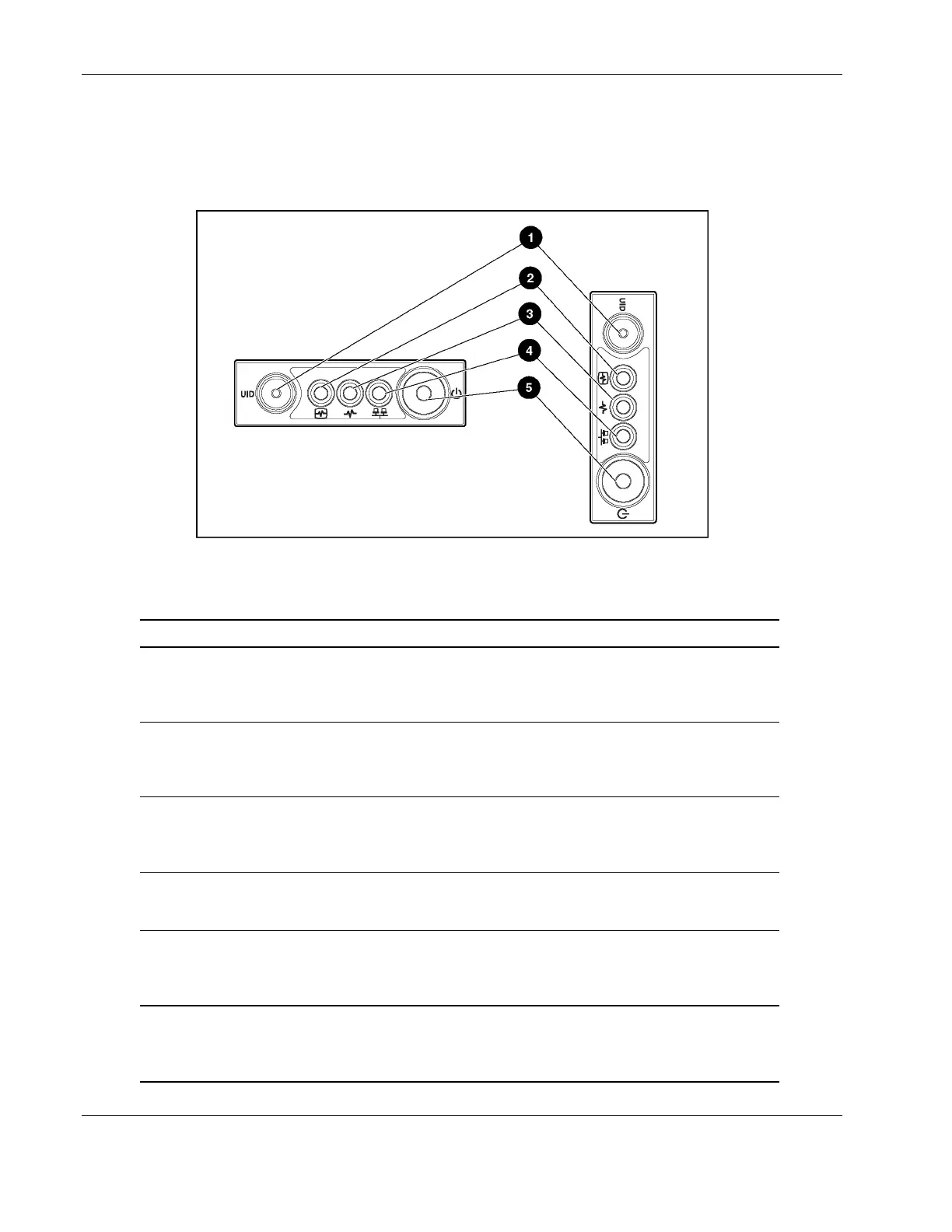
The set of five LEDs on the front of the server indicates system health. Figure 4-1 and
Table 4-1 identify and describe the location and function of each LED.
Figure 4-1: Front panel LEDs (rack and tower servers)
Table 4-1: Front Panel LEDs
Item Description Status
1 Unit identification (UID) switch and LED Blue = System activated
Blue flashing = System being managed
remotely
Off = System deactivated
2 Internal health LED* Green = Normal (system on)
Amber = System degraded
Red = System critical
Off = Normal (system off)
3 External health (power supply) LED Green = Normal (system on)
Amber = Redundant power supply failed
Red = Critical power supply failed
Off = Normal (system off)
4 Network LED (embedded NIC only) Green = Network link
Blinking = Network link/activity
Off = No network connection
5 Power On/Standby button and LED Amber = Power off (auxiliary power only)
Green = Power on
Off = Power cord not attached to the server
or the power supply failed
* The internal health LED identifies service events for internal components in a pre-failure or failed
condition. Internal components include fans, processors, PPMs, memory, and overtemperature
conditions. For a list of these events, refer to the HP ProLiant ML370 Generation 3 Server Setup
and Installation Guide.
4-2 HP ProLiant ML370 Generation 3 Server Maintenance and Service Guide
 Loading...