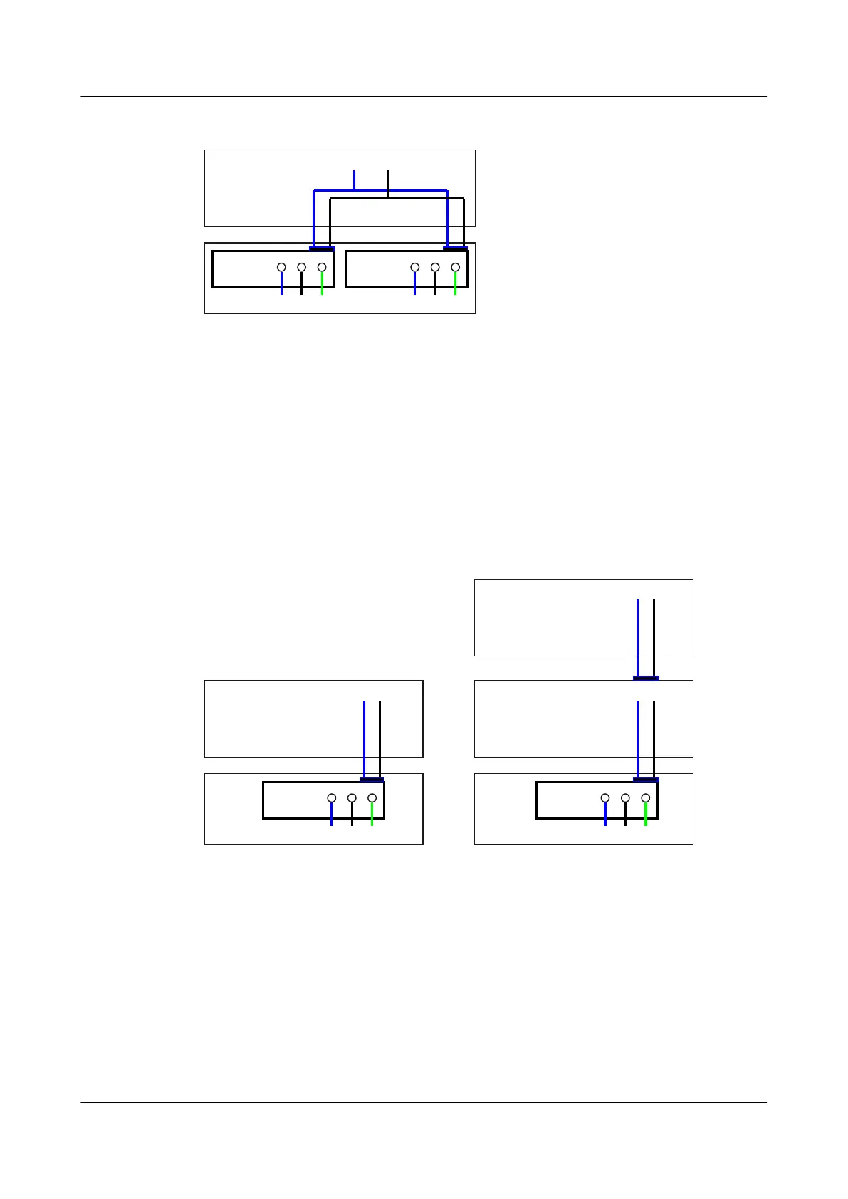
Figure 3-4 Layout of dual non-PoE AC power supply unit connection to motherboard
Motherboard
GND12V
PWR2PWR1
L N PGNDL N PGND
1. L: Live wire 2. N: Neutral wire 3. PGND: PGND wire 4. GND: Grounding
After the AC power is transmitted to the PWR module, the PWR module outputs 12 V voltage,
and then the motherboard provides power for the entire device.
3.2.5 Single Non-PoE + PoE AC Power Supply Unit
Figure 3-5 shows the layout of single non-PoE + PoE AC power supply unit connection to
motherboard.
Figure 3-5 Layout of single non-PoE + PoE AC power supply unit connection to motherboard
Motherboard
GND12V
PWR
L N PGND
PWR
L N PGND
RTN-53V
RTN-53V
PSE on the SRU
PoE Port (FE4~FE7)
1. L: Live wire
2. N: Neutral wire 3. PGND: PGND wire 4. GND: Grounding 5. RTN: Power ground cable
The non-PoE AC power supply unit and PoE AC power supply unit are independent of each
other:
l Non-PoE AC power supply unit: After the AC power is transmitted to the PWR module,
the PWR module outputs 12 V voltage, and then the motherboard provides power for the
entire device.
l PoE AC power supply unit: After the AC power is transmitted to the PoE module, the PoE
module outputs -53 V voltage, and then the PSE on the SRU provides power for the powered
devices (PDs) connected to the PoE interface.
Huawei AR1200&2200&3200 Series Enterprise Routers
Hardware Description 3 Power Supply Units
Issue 03 (2012-04-20) Huawei Proprietary and Confidential
Copyright © Huawei Technologies Co., Ltd.
34
 Loading...