Step 4 Connect cables to the front drive backplane. For details, see 3 Internal Cabling.
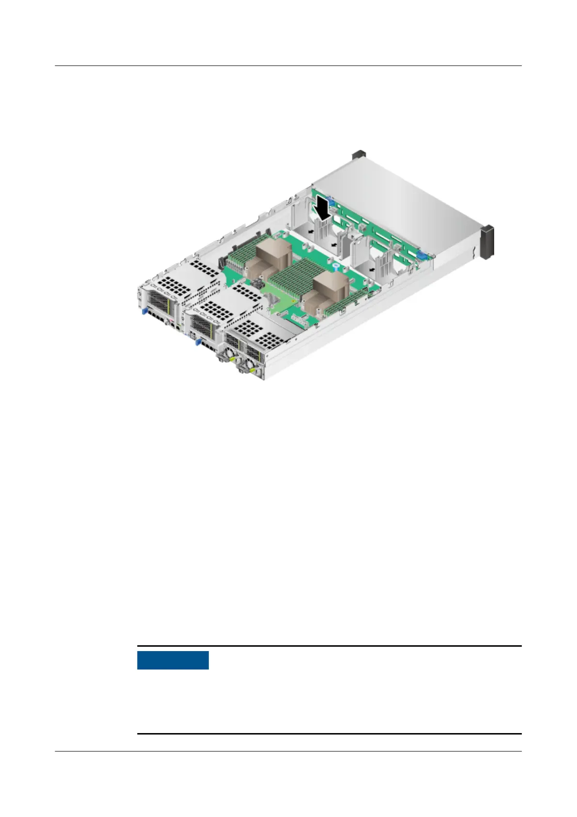
Step 5 Install all fan module brackets in the chassis. See Figure 5-81.
Figure 5-81 Installing a fan module bracket
Step 6 Install the fan modules. For details, see 5.10 Fan Module.
Step 7 Install front drives. For details, see 5.6 Drive.
Step 8 Install the air duct. For details, see 5.9 Air Duct.
Step 9 Install the chassis cover. For details, see 5.8 Chassis Cover.
Step 10 Install the server. For details, see 5.4.3 Installing the Server on Guide Rails.
Step 11 Connect the power cables. For details, see 5.7 PSU.
Step 12 Power on the server. For details, see 5.4.1 Powering On the Server.
Step 13 Log in to the iBMC WebUI, and check whether the new component is normal. For
details, see the
TaiShan Rack Server iBMC User Guide
.
----End
5.19 Rear Drive Module
This section uses the server with Kunpeng 920 7260, 5250, or 5230 processors as
an example to describe the internal structure of a server. The procedures for
removing and installing the rear drive module are the same for the server
congured with Kunpeng 920 5220 or 3210 processors.
TaiShan 200 Server
Maintenance and Service Guide (Model 2280) 5 Removal and Installation
Issue 04 (2020-01-16) Copyright © Huawei Technologies Co., Ltd. 141