Step 9 Connect cables to the drive module. For details, see 3 Internal Cabling.
Step 10 Install the chassis cover. For details, see 5.8 Chassis Cover.
Step 11 Install the server. For details, see 5.4.3 Installing the Server on Guide Rails.
Step 12 Connect the power cables. For details, see 5.7 PSU.
Step 13 Power on the server. For details, see 5.4.1 Powering On the Server.
Step 14 Log in to the iBMC WebUI, and check whether the new component is normal. For
details, see the
TaiShan Rack Server iBMC User Guide
.
----End
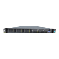
5.19.2 4 x 2.5-inch Rear Drive Module
Removing a Rear Drive Module
Step 1 Wear an ESD wrist strap. For details, see 5.2 ESD Protection.
Step 2 Power
o the server. For details, see 5.4.2 Powering O the Server.
Step 3 Remove the power cables. For details, see 5.7 PSU.
Step 4 Remove the server. For details, see 5.4.4 Removing the Server and Guide Rails.
Step 5 Remove the chassis cover. For details, see 5.8 Chassis Cover.
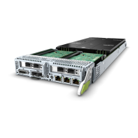
Step 6 Remove all cables from the rear drive module. For details, see 3 Internal Cabling.
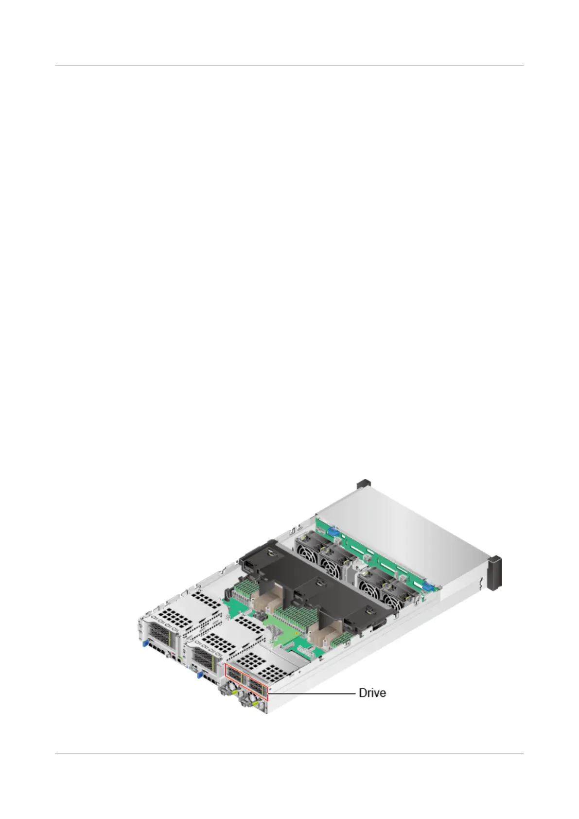
Step 7 Determine the positions of the drives in the rear drive module. See Figure 5-86.
Remove all drives from the rear drive module.
Figure 5-86 Positions of drives
Step 8 Loosen the screws that secure the rear drive assembly. See (1) in Figure 5-87.
TaiShan 200 Server
Maintenance and Service Guide (Model 2280) 5 Removal and Installation
Issue 04 (2020-01-16) Copyright © Huawei Technologies Co., Ltd. 145

 Loading...