199
Replacement Procedures and Illustrated Parts List
5. Cabinet Model: Install the paper path (page 235).
Pedestal Model: Install the top cover assembly (page 210).
6. Return the printer to normal operation (page 159).
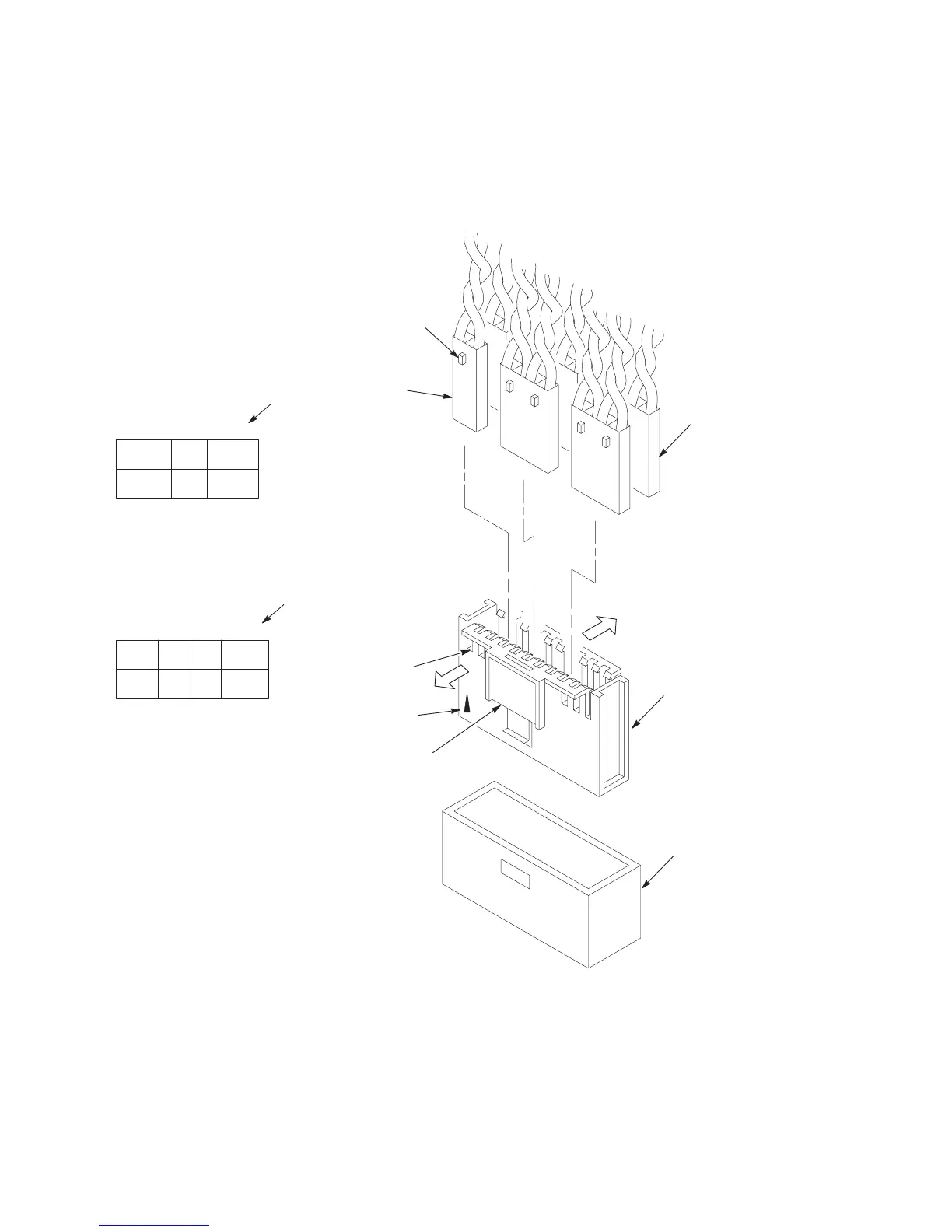
Housing, Connector Kit
PIN NO.
PIN NO.
(See
also page 297.)
P/N 14H5288
MPU = Magnetic Pickup
CVO = Cover Open (Switch)
PLO = Platen Open (Switch)
RRP = Right Ribbon Guide
EHF* = Exhaust Fan (Cabinet model)
HBF = Hammer Bank Fan
P
APR M = Paper Feed Motor
RRIB M = Right Ribbon Motor
* JMP on pedestal model (a spacer)
POD = Paper Out Detect (Switch)
PMD = Paper Motion Detect
(Switch)
CCF = Card Cage Fan
LRP = Left Ribbon Guide
PLA
T M = Platen Open Motor
LRIB M = Left Ribbon Motor
Pull the side outward just enough
to release the connector lock tab
from the slot in the connector
shell.
Typical
4-Wire
Cable
Connector
Key
Tab
Typical
2-Wire
Cable
Connector
Push here to
remove shell
from controller
board.
Pin 1
Key
Tab
Slot
Typical PCB
Connector
P106 Connector
Configuration
P107 Connector
Configuration
35791113151719 1
POD CCF PLAT
M
PMD LRP LRIB M
468101214161820 2
(T
op view; as seen when
plugged into the CMX
board.)
MPU PLO EHF
CVO RRP HBF
468101214161820 2
PAPR M
RRIB M
35791113151719 1
(T
op view; as
seen when
plugged into
the CMX
board.)
Figure 30. Cable Shell Connector, Disassembly/Assembly
 Loading...