242
Replacement Procedures and Illustrated Parts List
Resistors, Terminating
For parallel interface configurations, the printer is equipped with 470 ohm
pull-up terminating resistors and 1K ohm pull-down terminating resistors on
the controller board. These are suitable for most applications. (See
Figure 37, page 243.)
If the standard terminating resistor pack is not compatible with the particular
interface driver requirements of the host computer, other values of pull-up
and pull-down resistors may be required. 220 ohm pull-up and 330 ohm
pull-down alternate terminating resistors are provided with the printer. If you
install the 220 ohm pull-up resistor, you must also install the 330 ohm
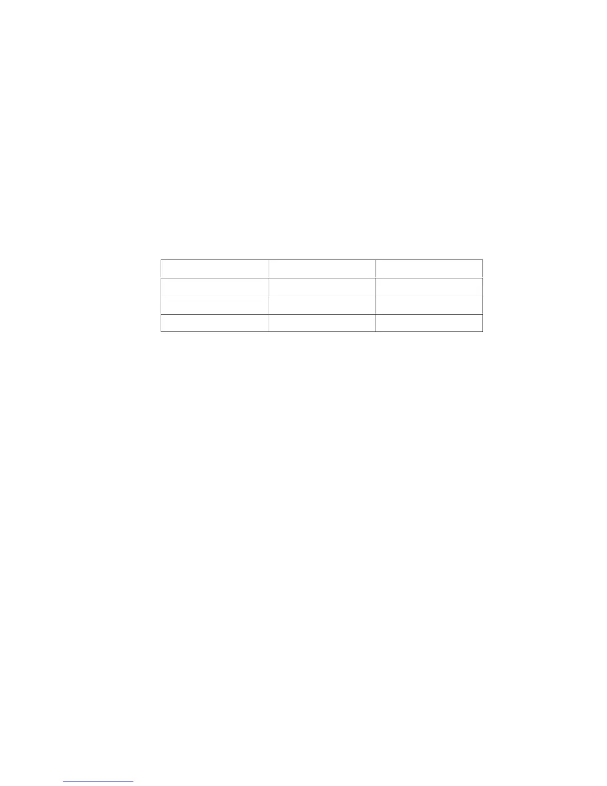
pull-down resistor. Possible terminating resistor combinations are shown
below.
Configuration
RP1 (Pull-Up) RP2 (Pull-Down)
Factory Default 470 Ohm 1K Ohm
Alternate 1 220 Ohm 330 Ohm
Alternate 2 1K Ohm None
Removal
ATTENTION
To prevent electrostatic damage to electronic components, wear a
properly grounded static wrist strap when handling circuit boards, the
shuttle frame assembly, and any other electronic component.
1. Prepare the printer for maintenance (page 158).
2. Cabinet Model: Remove the paper guide assembly (page 235).
Pedestal Model: Remove the top cover assembly (page 210).
3. Locate the terminating resistor packs. (See Figure 37.)
4. Using a chip puller, remove the packs.
Installation
ATTENTION
To prevent electrostatic damage to electronic components, wear a
properly grounded static wrist strap when handling circuit boards, the
shuttle frame assembly, and any other electronic component.
1. Using a chip installation tool, install the resistor packs in the correct
socket. (See Figure 37, page 243.)
2. Cabinet Model: Install the paper guide assembly (page 235).
Pedestal Model: Install the top cover assembly (page 210).
 Loading...