297Wire Data
IBM 6400
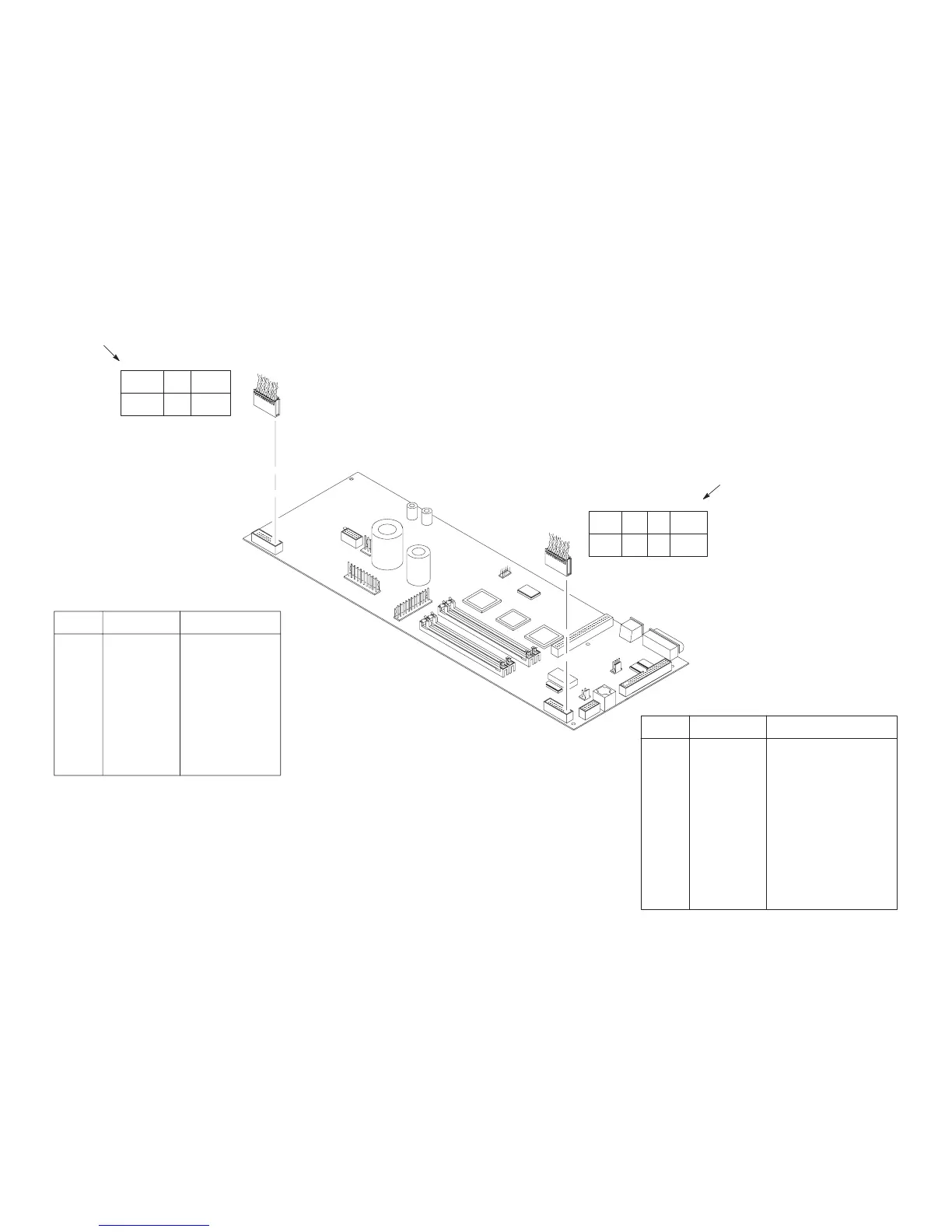
Main Wire Harness Test Tables
PIN NO.
PIN NO.
MPU PLO EHF
CVO RRP HBF
468101214161820 2
PAPR M
RRIB M
35791113151719 1
35791113151719 1
POD CCF PLAT
M
PMD LRP LRIB M
468101214161820 2
CCF
= Card Cage Fan
LRIB M = Left Ribbon Motor
LRP = Left Ribbon Post
PLA
T M = Platen Open Motor
PMD = Paper Motion Detect (Switch)
POD = Paper Out Detect (Switch
P107
CVO = Cover Open (Switch)
EHF* = Exhaust Fan
HBF = Hammer Bank Fan
MPU = Magnetic Pickup
P
APR M = Paper Feed Motor
PLO = Platen Open (Switch)
RRIB M = Right Ribbon Motor
RRP = Right Ribbon Post
*Only in cabinet models
P106
2, 4 and 6, 8
Normal
P106 Pins
LRIB M
Device
Resistance
7.2 – 8.8
Ω
PLAT
M
1, 3 and 5, 7
1.35 – 1.65
Ω
LRP
CCF
PMD
POD
10, 12
9, 1
1
14, 16
13, 15
Open across pins
Short across post
4.6 K
Ω
8 Meg
Ω
2, 4 and 6, 8
Normal
P107 Pins
RRIB M
Device
Resistance
7.2 – 8.8
Ω
PAPR M
1, 3 and 5, 7
0.417 – 0.681
Ω
HBF
EHF
RRP
PLO
10, 12
9, 1
1
14, 16
13, 15
2.7 K
Ω
Continuity: switch closed
Open: switch open
CVO
MPU
18, 20
17, 19
670
Ω
18, 20
Open
17, 19
8 Meg
Ω
Open
4.6 K
Ω
Open across pins
Short across post
Continuity: switch closed
Open: switch open
NOTE
: For cable shell connector
assembly/disassembly
, see
Figure 30 on page 199.
T
op view; as seen when plugged
into the CMX board.
T
op view; as seen when plugged
into the CMX board.
 Loading...