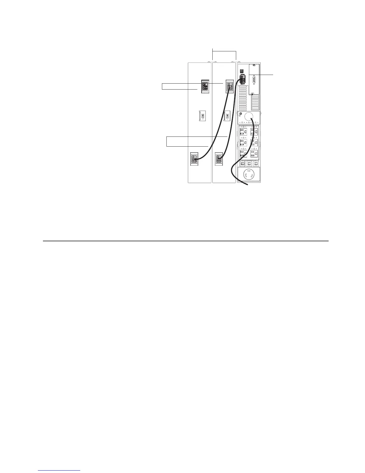
Extended battery
module cables
Extended battery module
battery connectors
Uninterruptible power supply
battery connector
Extended battery module brackets
2. Connect an extended battery module to the uninterruptible power supply using
an extended battery module cable (see the illustration in step 1 on page 12).
Connect one end of the extended battery module cable to an extended battery
module connector and then connect the other end to the uninterruptible power
supply battery connector. Crossing the cable as shown in the illustration is the
preferred method.
Completing the installation
To complete the installation of the uninterruptible power supply, complete the
following steps:
1. If you are installing power-management software, connect a workstation or
notebook computer to the uninterruptible power supply communication port
(COM connector on the Web/SNMP card) using the communication cable that
comes with the uninterruptible power supply.
2. Connect the devices that you want to protect into the applicable uninterruptible
power supply output receptacles. For information about load segments, see
“Load segments” on page 22.
Note: Do not protect laser printers with the uninterruptible power supply
because of the exceptionally high power requirements of the heating elements.
3. If an emergency power-off (disconnect) switch is required by local codes, see
“Remote emergency power-off installation” on page 14 to install the remote
emergency power-off switch before turning on the uninterruptible power supply.
4. Connect the uninterruptible power supply power cord to a power source. All
front panel LEDs flash briefly and then only the Power-on LED flashes,
indicating that the uninterruptible power supply is in Standby mode and the
connected devices are offline. If the alarm beeps or an uninterruptible power
supply General alarm LED stays lit, see Table 6 on page 39.
Chapter 2. Installing the uninterruptible power supply in a rack or tower configuration 13
 Loading...


