Web/SNMP card LEDs and controls
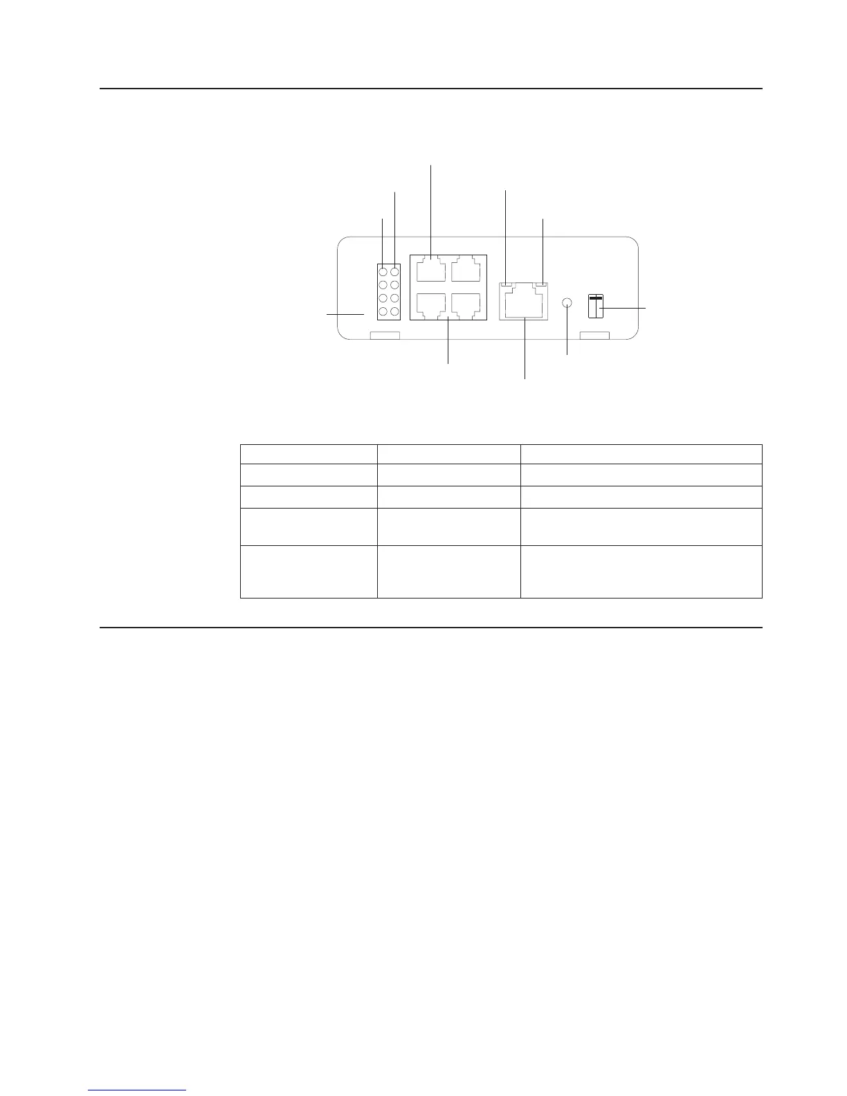
The following illustration shows the LEDs and controls on the Web/SNMP card.
10 Mb network LEDs (yellow)
DIP switch
Reset button
COM connector
1 2
Additional Ethernet Connectors
100 Mb network LEDs (green)
Status LED (yellow)
Power LED (green)
Uplink Ethernet connector
Off
On
Web/SNMP card
The Web/SNMP card LEDs are described in the following table.
Table 3. Web/SNMP card LED descriptions
Status LED 10 Mb or 100 Mb LED Card function description
Flickering On / Flickering Normal operation with Ethernet traffic
On On Web/SNMP card error
Off Off Uninterruptible power supply power is low
(no power to the Web/SNMP card)
Flashing
(approximately once
per second)
Flashing (approximately
once per second)
No connection to uninterruptible power
supply (alternate flashing as the
Web/SNMP card restarts)
Configuring the Web/SNMP card locally
Use the procedure in this section to access the Web/SNMP configuration utility
through a serial connector.
Before you begin
To use the configuration utility for the card, you need the following items:
v The DB9-to-RJ-45 cable that comes with the uninterruptible power supply
v A terminal with a serial communication port, or a computer with a terminal
emulation program. Set the serial line to 9600 baud, no parity, 8 data bits, 1 stop
bit, and no flow control.
Chapter 4. Using the Web/SNMP card 27
 Loading...


