Installing the front-panel assembly
To install the front-panel assembly, complete the following steps:
1. Position the front end of the front-panel assembly in the channel above drive
bay 1 on the left side of the chassis.
2. Push the front-panel assembly toward the front of the chassis until it clicks into
place.
3. Reroute and connect the front-panel assembly cable to the system board (see
“System-board internal connectors” on page 16 for the location of the
front-panel connector).
4. If the server has hot-swap power supplies, install the power-supply cage and
the power supplies (see “Installing the hot-swap power supply cage” on page
204).
5. Push the drives in bay 1 and bay 2 into the drive bays (see “Installing a DVD
drive” on page 156 for more information).
6. Install the upper bezel (see “Installing the upper bezel” on page 150).
7. Install the lower bezel (see “Installing the lower bezel” on page 148).
8. Install the side cover (see “Installing the side cover” on page 146).
9. Lock the side cover if you unlocked it during removal.
10. Reconnect the external cables and power cords; then, turn on the attached
devices and turn on the server.
Removing the front USB connector assembly
To remove the front USB connector assembly, complete the following steps:
1. Read the safety information that begins on page vii and “Installation guidelines”
on page 141.
2. Turn off the server and all attached devices; then, disconnect all power cords
and external cables.
3. Unlock and remove the side cover (see “Removing the side cover” on page
145).
4. Remove the lower bezel (see “Removing the lower bezel” on page 147).
5. Remove the upper bezel (see “Removing the upper bezel” on page 149).
6. Disconnect the front USB cable from the system board, and note the routing of
the cable (see “System-board internal connectors” on page 16 for the location
of the front USB connector).
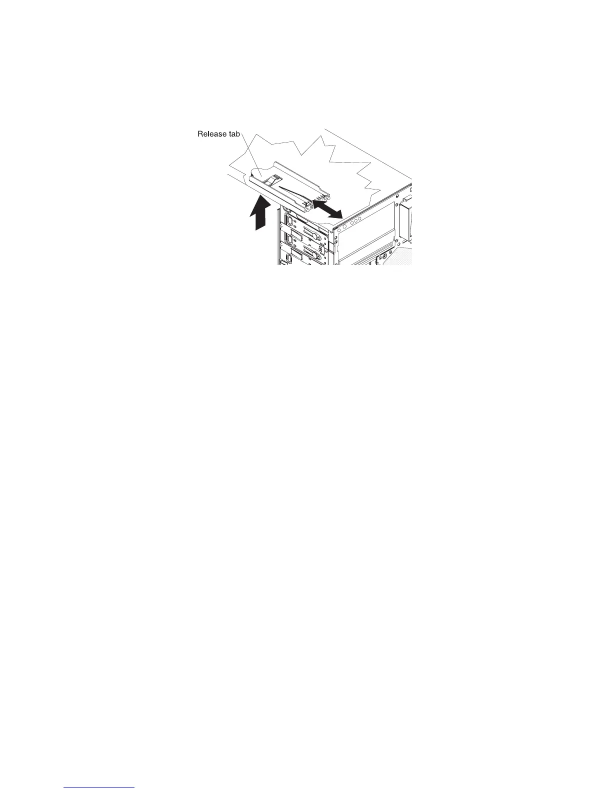
7. Press down and hold the release tab on the top of the front USB housing;
then, tilt the top of the housing away from the chassis and lift the housing out
of the opening in the chassis.
Chapter 5. Removing and replacing server components 199
 Loading...