6
2
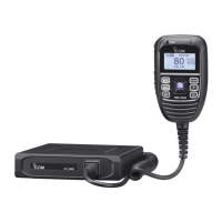
UNIT DESCRIPTION
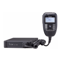
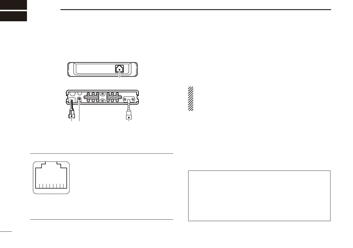
IC-440N Front and rear panels ■
q
w re
Front panel
Rear panel
q MICROPHONE CONNECTOR
Connects the supplied microphone or cloning cable (OPC-
1122U.)
q DC output (same voltage as connected
battery or DC power supply)
w TX line
e GND
r PTT
t GND (microphone ground)
y AF line
u POWER
i RX line
w POWER RECEPTACLE
Accepts 13.8 V or 27.6 V DC with the supplied DC power
cable.
+ red
_ black
NOTE: DO NOT use a cigarette lighter socket as a power
source when operating in a vehicle. The plug may cause
voltage drops and ignition noise may be superimposed
onto transmit or receive audio.
e EXTERNAL SPEAKER JACK [SP]
Connects a 4 speaker. (p. 4)
• Audio output power is typically 5.0 W.
r ANTENNA CONNECTOR
Connects a 50 antenna with a PL-259 connector and a
50 coaxial cable.
ANTENNA INFORMATION
For radio communications, the antenna is of critical impor-
tance, to maximize your output power and receiver sensitiv-
ity. The transceiver accepts a 50 antenna and a less than
1:1.5 Voltage Standing Wave Ratio (VSWR).
High SWR values not only may damage the transceiver,
but also lead to TVI or BCI problems.
qi
Front panel view
 Loading...