77
9
OTHER FUNCTIONS
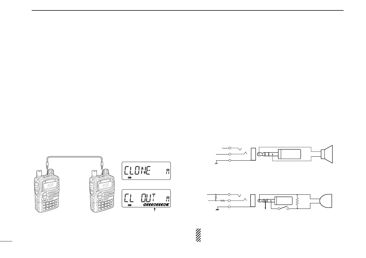
■ Cloning function
The IC-E90 has transceiver-to-transceiver data cloning capa-
bility. This function is useful when you want to copy all of the
programmed contents from one IC-E90 to another.
• An optional OPC-474
CLONING CABLE is required.
q Connect an optional OPC-474 between both [SP] jacks.
w While pushing [8 SET] and [MR], push [PWR] for 1 sec. to
enter cloning mode.
• “CLONE” appears.
e Push [PTT] on the “master” transceiver.
• “CL OUT” appears and the signal indicator shows that cloning is
taking place.
r Push [PWR] for 1 sec. to turn power OFF.
The optional CS-T90A
CLONING SOFTWARE and the optional
OPC-478
CLONING CABLE are available to clone and edit
contents with a PC (for Microsoft
®
Windows
®
95/98 and ME).
Microsoft
®
and Windows
®
are registered trademarks of Microsoft Corporation in
the U.S.A. and other countries.
■ [SP/MIC] jacks
To connect external equipment such as speaker, microphone,
TNC, etc. refer to the diagram below.
The center terminal of [MIC] outputs 3.2 V DC via 330 Ω
register.
 Loading...