Basic Operation
2. Set pin 4’s function to Not-Invert and Trig-In→List.
3. Recall the edited List file for trigger running.
4. Set ListTrig Source to External.
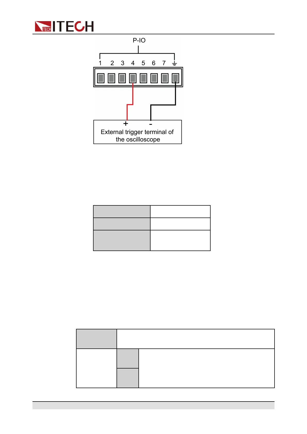
5. Send pulse signals as per the following requirements from the external
oscilloscope to pin 4.
Level rise slope 10us
Level fall slope 2us
Minimum time width
for low level keep
30us
6. Observe the VFD screen on the instrument’s front panel to confirm
whether the List file is running or not.
5.11.5 IO–5. INH-Living, Not-Invert
Parameter Description
IO–5. Living,
Not-Invert
Parameter setting for pin 5.
Not-
Invert
Indicates whether to invert the input/output pulse or
level signal.
• Invert: Yes
• Not-Invert: No
Invert
Copyright © Itech Electronic Co., Ltd.
90

 Loading...


