Basic Operation
– Under default conditions (pin 5 is not connected), it will not effect the in-
strument’s input state.
– If [On/Off] is in On state, when pin 5 receives pulse signal, [On/Off] will
be turned off: The [On/Off] button light is lighted off, and the VFD indica-
tor light displays Off.
After confirming that the [On/Off] can be turned on again, the user needs
to manually turn on [On/Off].
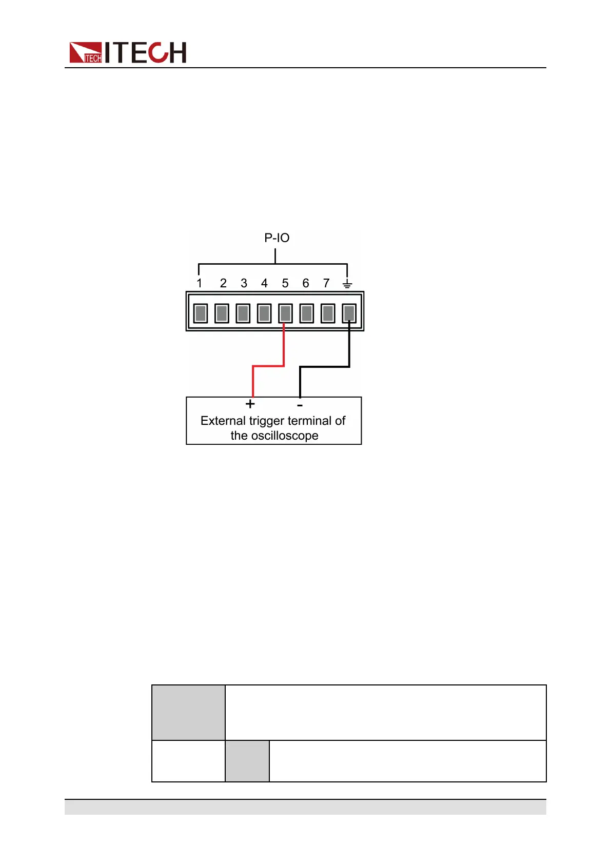
1. Referring to the figure below, connect pin 5 to the external oscilloscope.
2. Set pin 5’s function to Not-Invert andInhibit→Latch.
3. Set voltage to 10V and turn on [On/Off].
4. Input pulse signal to pin 5.
At this point, the [On/Off] button light is lighted off, and the VFD indicator
light on the front panel displays Off, and the input function is switched
off. In addition, the VFD screen on the front panel displays Inhibit-Ps.
When the protection state is cleared, manually turn on [On/Off] again.
5.11.6 IO–6. Sync-On, Not-Invert
Parameter Description
IO–6. Sync-
On, Not-
Invert
Parameter setting for pin 6.
Not-
Invert
Indicates whether to invert the input/output pulse or
level signal.
Copyright © Itech Electronic Co., Ltd.
93

 Loading...


