Basic Operation
If pin 5 is set to Invert, input high level to pin 5, and it will impact the input
state.
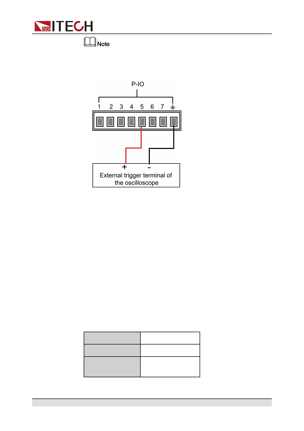
1. Referring to the figure below, connect pin 5 to the external oscilloscope.
2. Set pin 5’s function to Not-Invert andInhibit→Living.
3. Set voltage to 10V and turn on [On/Off].
4. Input low level to pin 5.
At this point, the [On/Off] button light is lighted on, and VFD indicator
light on the front panel displays On, while voltage/current Meter value
gradually decreases to 0, the input function is prohibited. In addition, the
VFD screen on the front panel displays INH.
5. Input high level to pin 5.
At this point, [On/Off] button light is lighted on, and VFD indicator light on
the front panel displays On, and voltage/current Meter value gradually re-
covers to 10V, and the input function is re-initiated.
• When pin 5 is set to Inhibit-Latch (Not-Invert), pin 5 can control the instru-
ment’s input state based on the pulse signal from external input. The param-
eter requirements of this pulse signal are as follows:
Level rise slope 10us
Level fall slope 2us
Minimum time width
for low level keep
30us
Copyright © Itech Electronic Co., Ltd.
92

 Loading...


