Quick Reference
Pins Description
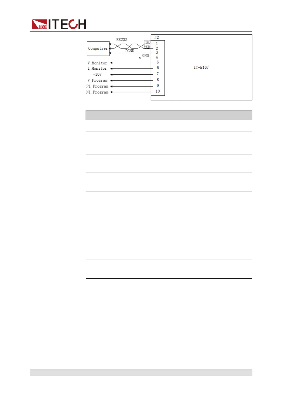
1 RS-232 TXD pin for transmitting data.
2 RS-232 RXD pin for receiving data.
3 RS-232 DGND pin for grounding.
4 Ground terminal, that is, the negative terminal of pin 5 to pin
10.
5 Voltage monitoring terminal. It can output a voltage of 0 to
10V to monitor the input voltage from 0 to full scale.
6 Current monitoring terminal.
It can output a voltage of 0 to 10V to monitor the output cur-
rent from 0 to full scale input current.
7 Reference voltage (10V) test terminal. The accuracy is
0.03%. You can use a multimeter to measure this pin. When
the output voltage of the pin is in the range of 10±0.03%*10, it
indicates that the accessory is functioning normally. Other-
wise, the function is abnormal and cannot be used.
8 / 9 /
10
Terminals for external analog function. For details, see 5.12
Analogue Function (Ext-Program) (Optional).
• Fiber optic modules and cables
Fiber optic modules and cables are used for data transmission and commu-
nication between parallel units, and are highly resistant to interference. The
fiber optic module and cable are the necessary accessories for the parallel
connection. Different numbers of fiber optic modules and cables are used in
different numbers of parallels.
Copyright © Itech Electronic Co., Ltd.
16

 Loading...


