Inspection and Installation
Definition of RS-232 Pins
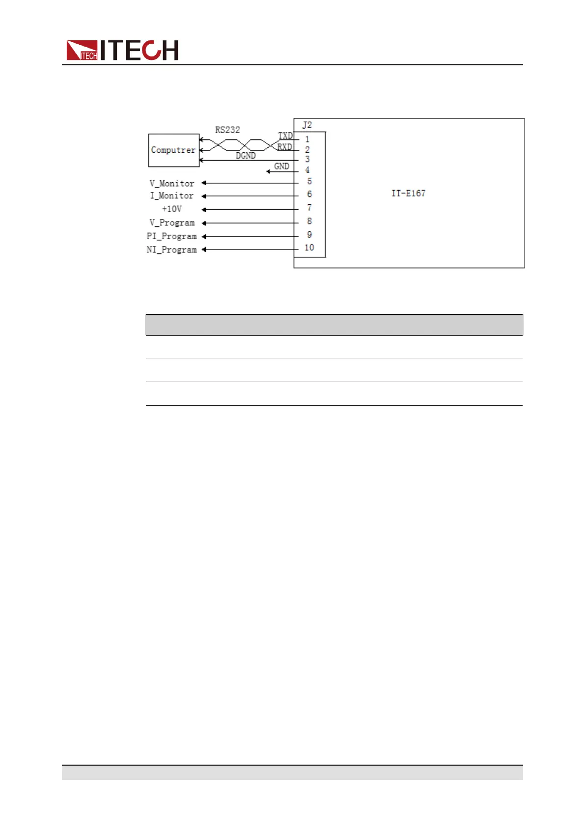
The definition of RS-232 pins are as follows.
When using the RS-232 interface for communication, connect the pin 1, pin 2,
and pin 3 of the IT-E167 to the PC. The pin description is as follows:
Pins Description
1 TXD, transmit data
2 RXD, receive data
3 DGND, ground
RS–232 Configuration
When you purchase the interface accessory and successfully insert it into the
corresponding position on the rear panel of the instrument, the RS–232 menu
item will appear in the System menu. The specific steps are as follows:
1. Ensure that the instrument's power switch is off, that is, the instrument is in
Power Off state.
2. Insert the separately purchased RS–232 interface card into the card slot on
the rear panel of the instrument.
3. Connect the instrument to the computer via an RS–232 cable. After the con-
nection is successful, turn on the power switch of the instrument.
4. Press the composite keys [Shift]+[P-set] (System) on the front panel to en-
ter the system menu.
5. Rotate the knob or press the Up/Down key to select I/O and press [Enter].
6. Press the Left/Right key to select RS232 and press [Enter].
7. Set the relevant communication parameters in turn, and press [Enter].
The RS–232 interface parameters are as follows.
Copyright © Itech Electronic Co., Ltd.
38

 Loading...


