Basic Operation
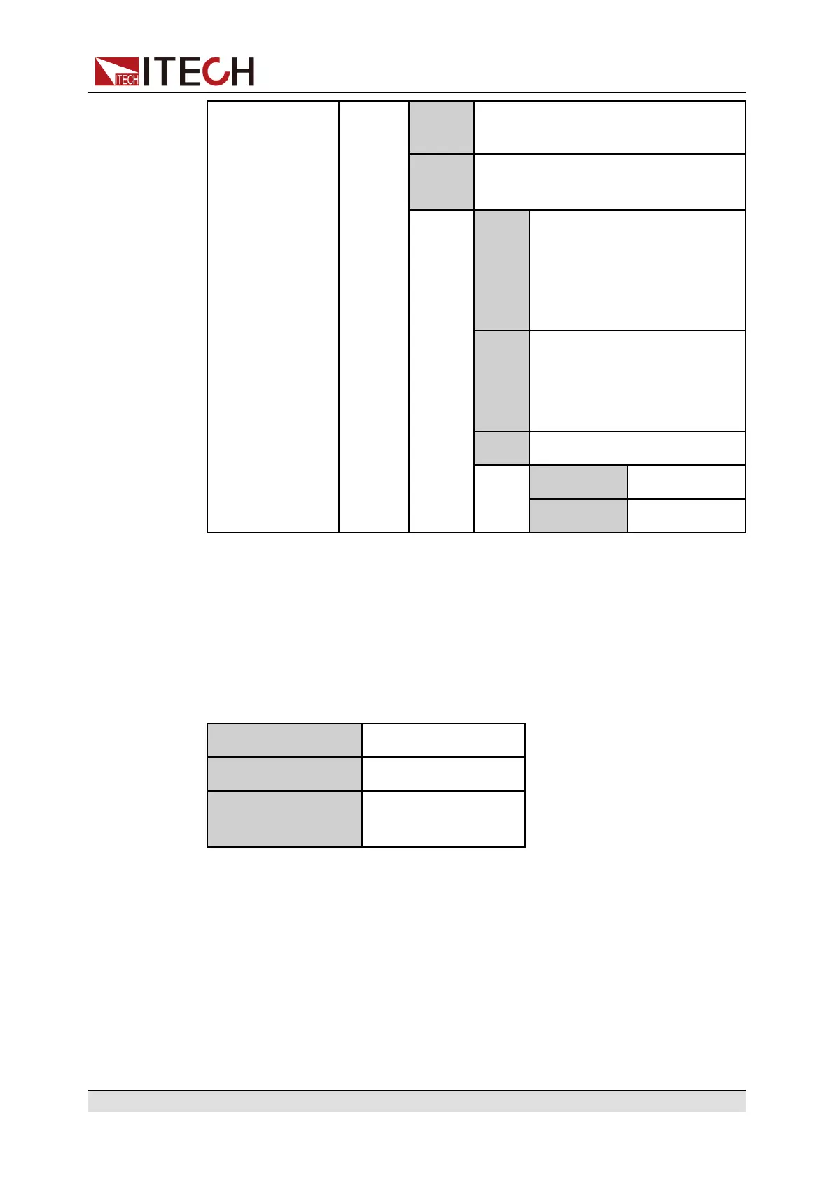
Input Pin 1 receives the level signal from
the outside.
Output Pin 1 sends the digital signal (1, 0,
PWM) to the outside.
True By default (Not-Invert), the
output digital signal is 1 (i.e.
low level), and in the case of
Invert, the output is high
level.
False By default (Not-Invert), the
output digital signal is 0 (i.e.
high level), and in the case of
Invert, the output is low level.
PWM Digital signal of PWM.
PWM Freq Frequency
PWM Duty Duty cycle
How to Use
When pin 1 is set to default Ps-Clear function, pin 1 has bi-directional I/O func-
tion, which can receive pulse signal input from the external instrument and also
can output pulse signal to external instrument. Pulse signal parameter require-
ments are as follows:
Level rise slope 10us
Level fall slope 2us
Minimum time width
for low level keep
30us
• Pulse input: When the instrument is under protection, the instrument will
clear protection after receiving the pulse signal from external input.
1. Refer to the figure below to connect pin 1 to the external oscilloscope.
Copyright © Itech Electronic Co., Ltd.
82

 Loading...


