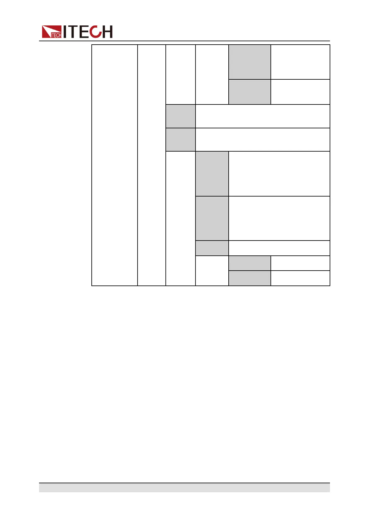
Basic Operation
Dlog Triggers the run-
ning of data re-
cording function.
List Triggers the run-
ning of List files.
Input Pin 4 receives the level signal from the
outside.
Output Pin 4 sends the digital signal (1, 0, PWM)
to the outside.
True By default (Not-Invert), the out-
put digital signal is 1 (i.e. low
level), and in the case of Invert,
the output is high level.
False By default (Not-Invert), the out-
put digital signal is 0 (i.e. high
level), and in the case of Invert,
the output is low level.
PWM Digital signal of PWM.
PWM Freq Frequency
PWM Duty Duty cycle
How to Use
Taking the triggering of List function as an example, the text below will introduce
how to use pin 4’s default function Ext-Trig.
• Trig–Out
1. Refer to the figure below to connect pin 4 to the external oscilloscope.
Copyright © Itech Electronic Co., Ltd.
88

 Loading...


