Maintenance Guide
1-29
Figure 1-8-6-1
1-8-5. Removing the Y Veyor-Cable
(1) Disconnect the binding of the swing part (connector bracket) at the entrance of the Y-axis
plastic rail and the relay connector.
Figure 1-8-5-1
(2) Detach the cover of the Y plastic rail and remove the cable to be replaced.
Figure 1-8-5-2
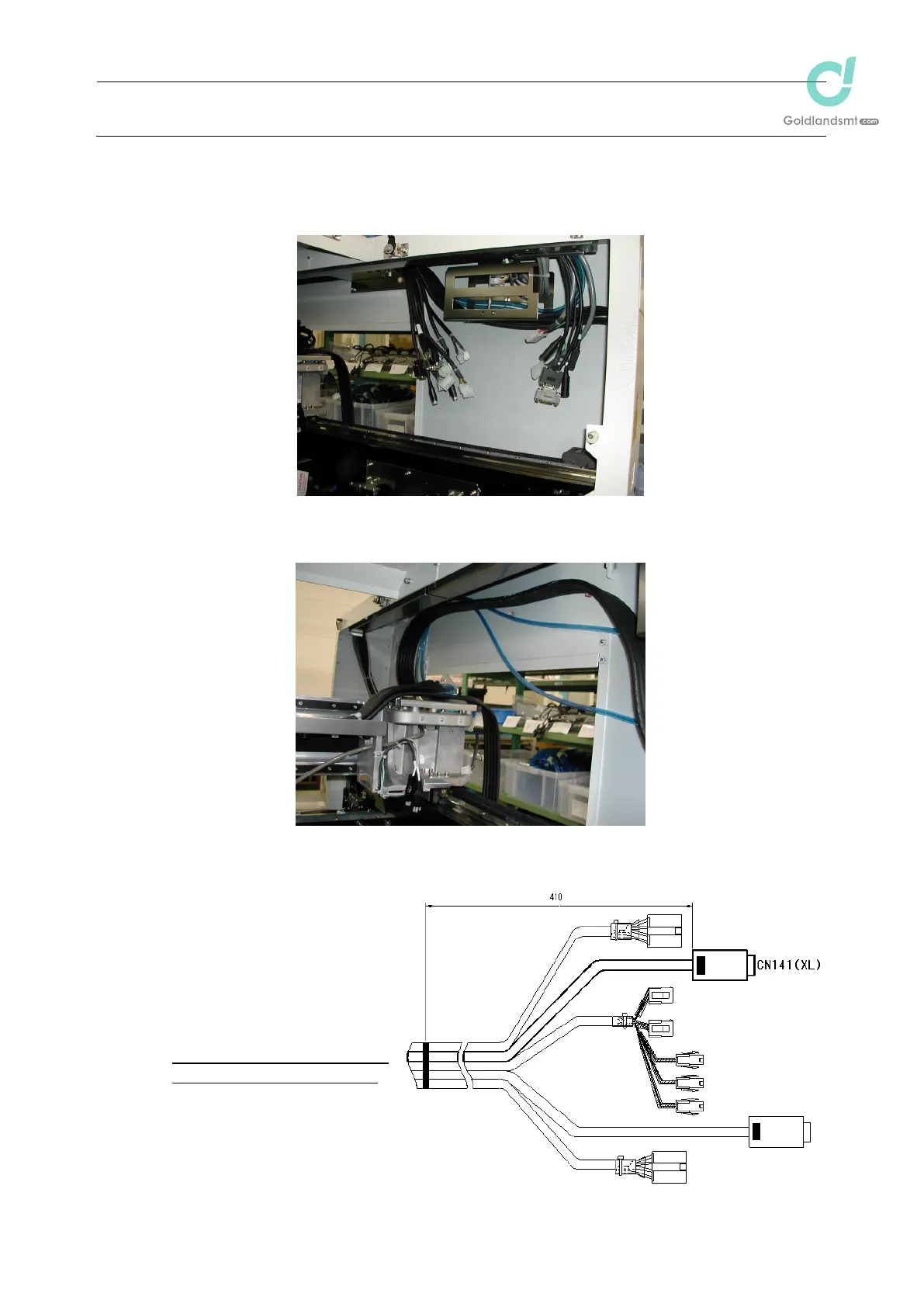
1-8-6. Placing Marks on the Y Veyor-Cable
(1) Check the marking position
of the Y veyor-cable (40058384).
(Place marks at a position
410mm from the end of the
CN141 connector.)
For the machine with the extra
specifications, the following cables
are used.
XY veyor-cable (E) 40059779
Y veyor-cable (E) 40059789
This instruction also applies to
the following pages.

 Loading...


