Maintenance Guide
2-18
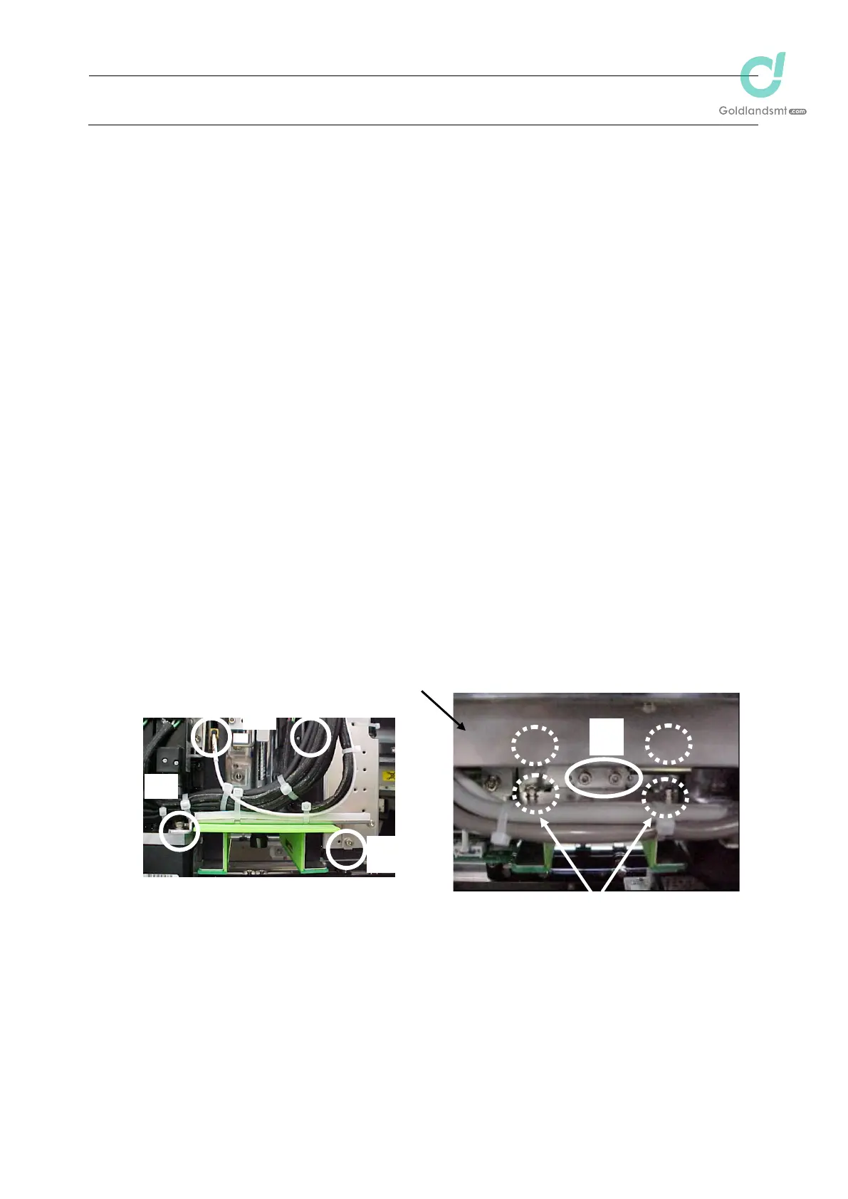
2-5-3. Replacing the FMLA (KE-2080R)
After the LA sensor has been replaced, it is absolutely necessary to re-input the MS parameters
related to the laser. (See section 2-9.)
After the replacement work has been completed, clean the laser window of the LA sensor with a
clean cloth rag.
(1) Remove the magnescale guard c of the X-axis.
(2) Remove the M4 u 8 SEMS cap bolts (3 pcs.) d and M3 u 6 SEMS cap bolt (1 pc.) e
mounting the diffuser base to disconnect the LA cable connectors f (3 pcs.) from the
sensor.
(3) Detach the diffuser and remove the screws g (4 pcs.) mounting the sensor in the broken
line portion of the Figure.
(4) Reassemble the components in the reverse order of disassembly.
Apply Loctite 242 to the sensor mounting screw
g (4 pcs.) and tighten them with a
tightening torque of 2.3 Nm.
When attaching the sensor, insert the pin into the positioning hole of the bracket first.
Then fix the sensor.
For details about adjustment of clearance at the diffuser mounting position, see QA
Table, Head 12.
Figure 2-5-3
e
d
c
d
f
g
Front view of IC head
Rear view of IC head

 Loading...


