Maintenance Guide
2-3
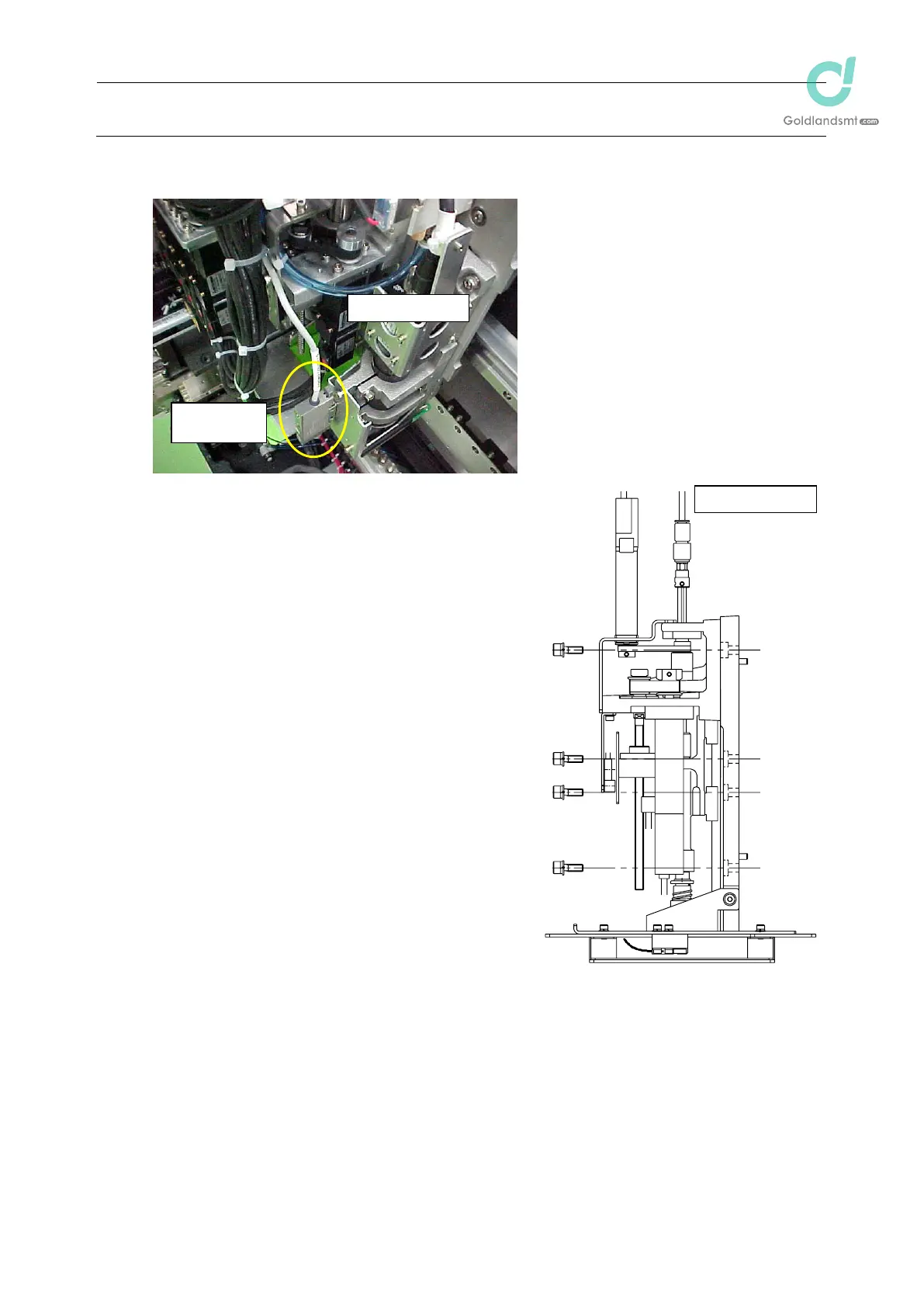
2-1-2. IC Head (KE-1080/2080)
(1) Disconnect the Zș-motor cables from the servo
amplifier board.
(2) Disconnect the Z-sensor cables from the head
main board.
(3) Disconnect the fibers (2 pcs.) from the point
sensor amplifier and detach the amplifier main
unit from the bracket.
(4) Disconnect the I4 and I6 air tubes.
(5) Detach the release bar. (See also section 2-5.)
(6) While keeping the IC head by hand so that it does
not fall down, remove the M5 u 16 SEMS cap
bolts (6 pcs.).
(7) Pull out two parallel pins. Raise the IC head so
that it is not in contact with other components, and
then detach it.
(8) Reassemble the components in the reverse order
of disassembly.
Apply Loctite 242 to the IC head mounting
screws (6 pcs.) and tighten them with a
tightening torque of 7.0 N
㺃m.
(9) After the head has been replaced, it is necessary
to input the MS parameters again. For details
about input items, see section 2-9.
Figure 2-1-5

 Loading...


