Maintenance Guide
1-14
1-4-2. Clearance of the Magnescale
(1) Put the MSC clearance jig (part No. 40008106) with a thickness of 0.25 mm in the
clearance between the magnescale and sensor head, and then tighten the screw again.
(2) Check that the MSC clearance jig with a thickness of 0.35 mm is not put in the clearance
between the magnescale and sensor head in the XY-axes full-stroke.
(3) In the same manner, check that the MSC clearance jig 0.15 (part number: 40073350)
with a thickness of 0.15 mm can be put in the clearance between these devices.
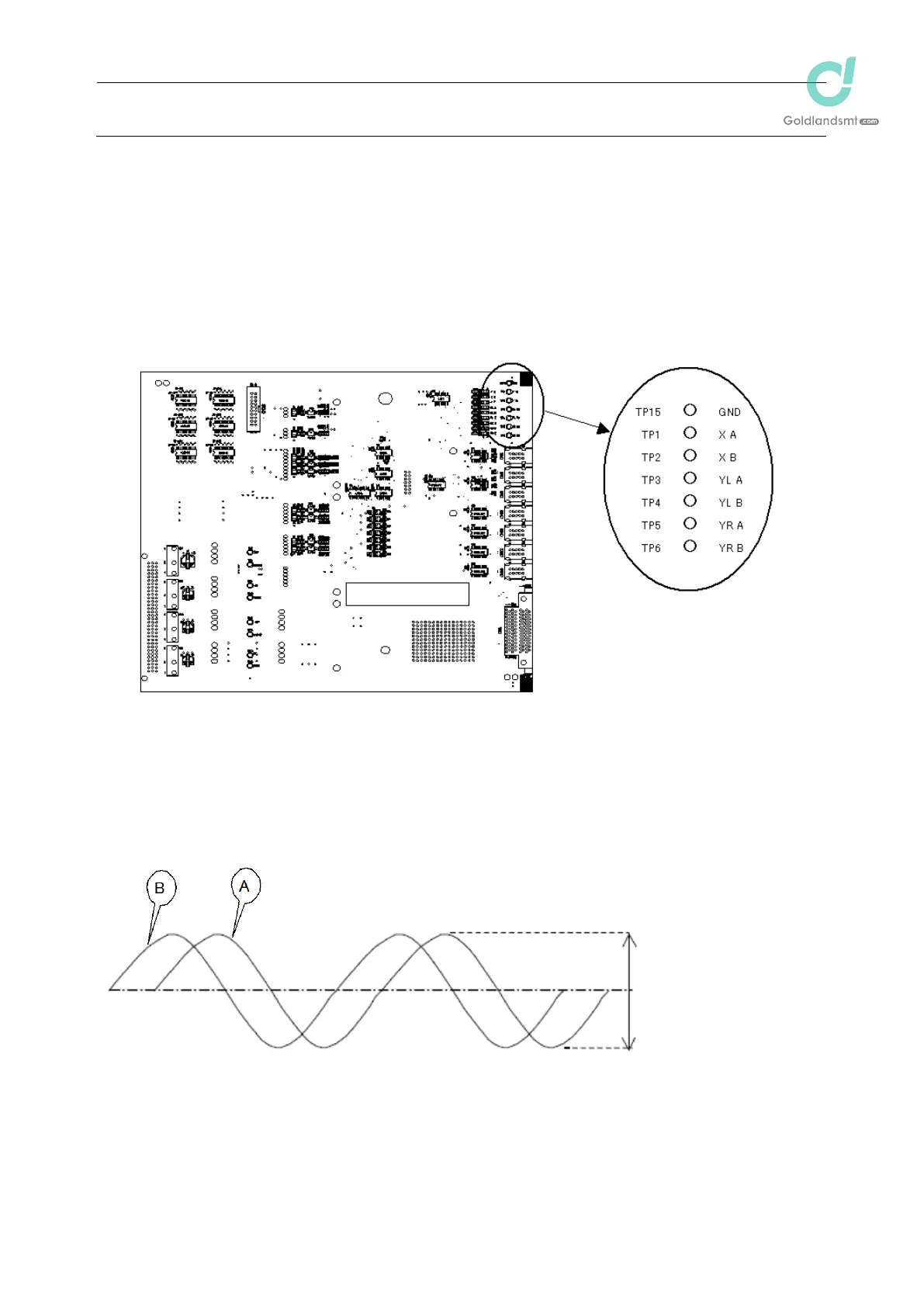
(4) Use the test pins on the XY RELAY board (part No. 40044556) shown in the figure below.
Note) Detach or attach the cover and probe with the power turned OFF.
(5) For every axis, connect the probe of the oscilloscope to the GND terminal "GND (TP15)",
"XA (TP1)", "YLA (TP3)" or "YRA (TP5)" respectively to measure the voltage waveform. At
this time, observe the amplitude of the A-phase and B-phase waveforms shown on the
oscilloscope to make sure that the P-P value is 2.0V±0.5V in the entire area.
Each amplitude
1.5 to 2.5Vpp
(In the recommended
mounting status)
XY RELAY board

 Loading...


