Maintenance Guide
3-4
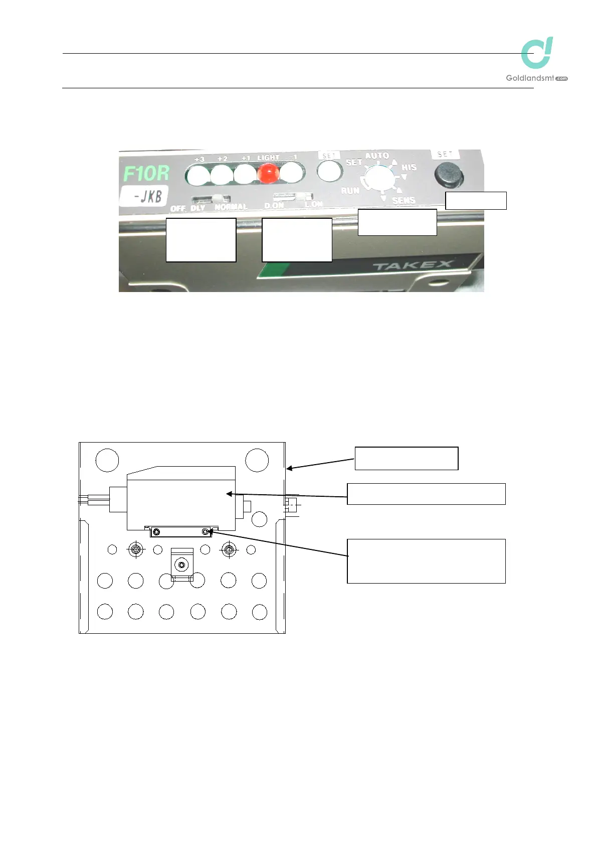
3-2-5. Setting the Switches on the Bad Mark Sensor Assembly (F10R Amplifier)
Use the bad mark sensor assembly with the settings made before shipment from the factory
(default settings).
Figure 3-2-4 Switch Settings
3-2-6. Assembling and Setting the F70R Fiber Sensor Amplifier
The assembling method varies depending on the M/C Rev. Perform replacement
operations after checking the M/C Rev. (For assembly of earlier models than M/C Rev. L,
40063956: AMP BRACKET is used.)
Amplifier mounting (after M/C Rev. M)
SET button
Mode switch
o AUTO
Operation mode
selector switch
o L ON
Output timer
selector switch
o NORMAL
LNC60 motor cover
Bad mark sensor amplifier (F70R)
4006356: AMP BRACKET
Accessories: DIN rail
Hexagon socket head bolt (x 2)

 Loading...


