Maintenance Guide
2-15
2-5. Replacing the Laser Sensor
2-5-1. Replacing the LNC
After the LNC has been replaced, it is absolutely necessary to re-input the MS parameters related
to the laser. (See section 2-9.)
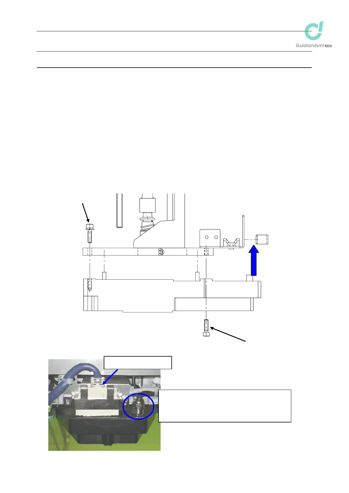
(1) Disconnect the connectors (encoder and IEEE1394) and remove the mounting screws c
and d (3 pcs.) to detach the LNC.
(2) Reassemble the components in the reverse order of disassembly.
Before mounting the components, remove Loctite sticking to the sensor bracket as
much as possible.
When attaching the sensor, insert the sensor pin into the positioning hole of the
bracket first. Then fix the sensor.
Apply Loctite 242 to the sensor mounting screws
c and d and tighten them with a
tightening torque of 2.6 Nm.
After the LNC has been replaced, clean the laser beam window of the LNC with a
clean cloth rag.
Figure 2-5-1
Connectors
d (2 pcs.)
ș-encoder connector
Pay special attention so that this connector is
not disconnected.
1394-relay connector is located on the rear of
the bracket fixing the encoder connector.
c

 Loading...


