Maintenance Guide
3-2
3-2. Replacing the Bad Mark Sensor
3-2-1. Sensor Assembly
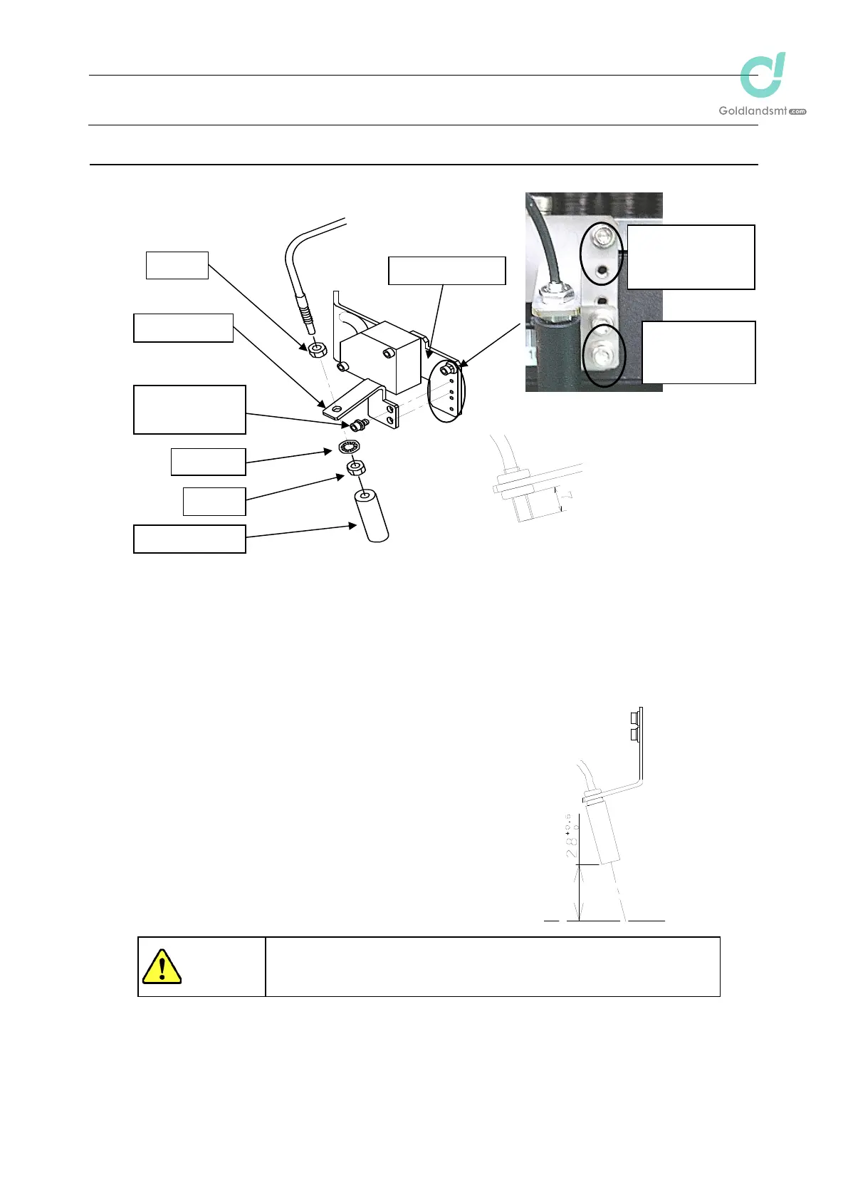
Figure 3-2-1 Replacing the Bad Mark Sensor
Secure the fiber with the nut and washer supplied with the fiber. After the fiber is secured as
illustrated in the figure above, mount the zoom lens.
3-2-2. Adjusting the Sensor Height
Move the bad mark sensor to a point above the calibration
block. Loosen the SEMS cap bolts at two places and move the
BM lens holder so that the distance between the surface of the
bad mark sensor and the top surface of the calibration block
becomes 28 mm. When the specified distance is reached,
secure the bad mark sensor with SEMS cap bolts.
After the bad mark sensor has been mounted, input a bad
mark sensor offset of the MS parameters. (For details about
how to input MS parameters, see "MS Parameters".)
㻌
To prevent personal injury, do not put your hand inside the machine
or your face or head close to the machine during operation of the
HOD.
㻯㻭㻸䢈䢚䢗䡫䡴
ୖ㠃
BM lens holder䢢
SEMS cap
CAL block top
surface
+05
0
HMS bracket
Nut
M3u6 SEMS
cap (u2)
BM holder
Washe

 Loading...


