Maintenance Guide
2-22
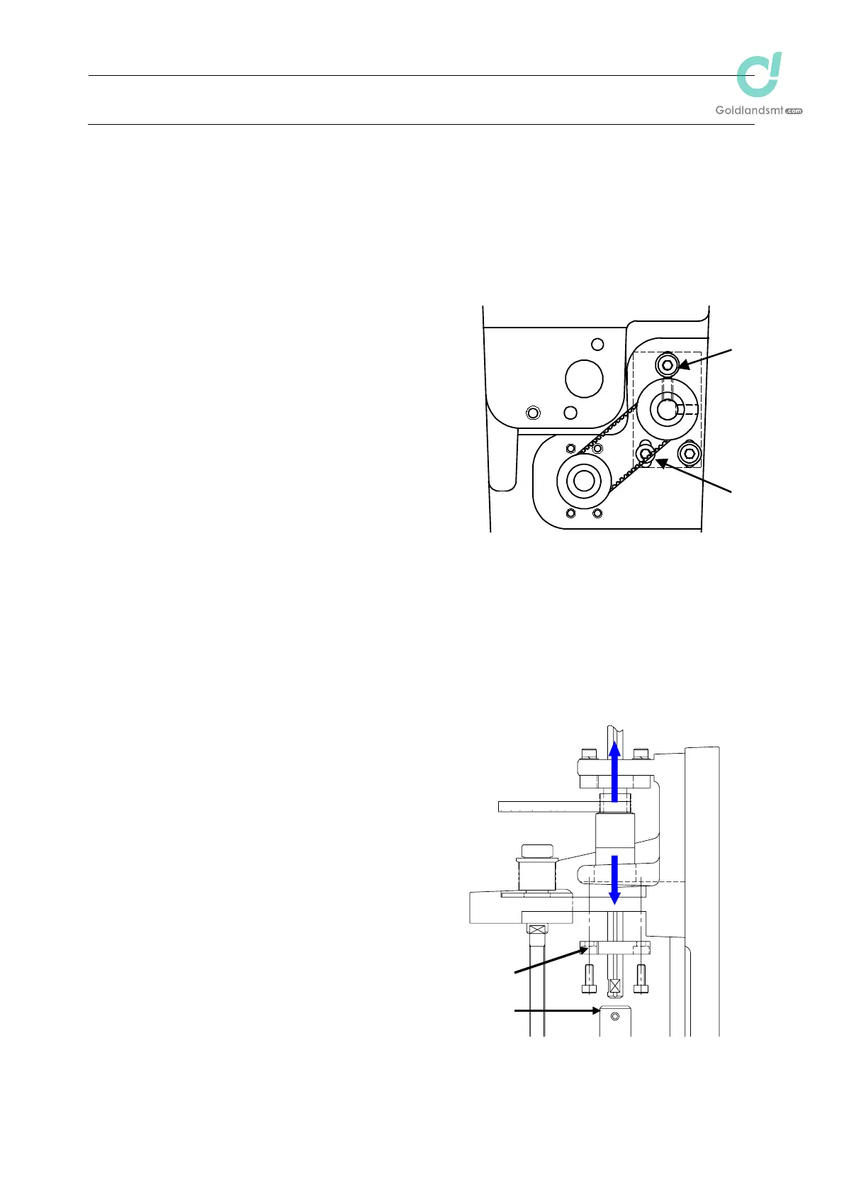
2-7-2. IC Head
<Replacing the timing belt Z IC>
After the timing belt Z IC has been replaced, it is absolutely necessary to re-input the MS
parameters related to the Z-axis home position adjustment, Z-axis height, and laser. (For details
of input items, see section 2-9.)
(1) Loosen the screws c and d (3 pcs.) shown in
the figure on the right.
(2) Replace the timing belt Z IC.
(3) Reassemble the components in the reverse
order of disassembly.
Apply Loctite 242 to the Z-motor mounting
screws (3 pcs.) and tighten them with a
tightening torque of 2.3 Nm.
Adjust the belt tension following section
2-2-1.
<Replacing the timing belt T: KE-1080/2080>
After the timing belt T has been replaced, it is absolutely necessary to re-input the MS parameters
related to the Z-axis home. (For details of input items, see section 2-9.)
(1) Detach the bearing base L c.
(2) Detach the spline shaft from the coupling d.
(3) Pull out the spline housing downward and
the spline shaft upward.
(4) Replace the timing belt T.
(5) Reassemble the components in the reverse
order of disassembly.
When the bearing base L is secured,
make sure that the shaft is rotated
smoothly.
When inserting the spline shaft into the
coupling, secure the spline shaft with it
kept pushed-in.
Adjust the belt tension following section
2-2-4.
Figure 2-7-3
c
d
Figure 2-7-4
c
d
Timing belt T

 Loading...


