Maintenance Guide
2-17
<Adjusting the offset and sensitivity of the point sensor>
(1) Before starting the adjustment, set the sensitivity change-over switch to “NORM” and the
response time change-over switch to “FAST”.
(2) Connect “+” and “-“ of the voltmeter to the check terminals TP23 and TP21 on the HEAD
MAIN PCB ASM, respectively.
(3) Set the span adjustment controller of the sensor amplifier to “MAX” and the offset
adjustment controller to “MIN”.
(4) Interrupt the light between the light emitting and receiving parts of the fiber unit completely.
(At this time, do not use any light transmission material, such as paper sheets.)
(5) While carefully observing the voltmeter, gradually turn the offset adjustment controller
toward “MAX” to adjust the voltage value to “1V±0.01V”.
(6) Then put the status between the light emitting and receiving parts to the light receiving one.
(7) While carefully observing the voltmeter, gradually turn the span adjustment controller toward
“MIN” to adjust the voltage value to “5V±0.05V”. The voltage output is about 7.3V when the
span adjustment controller is set to Max with maximum light emitting.
(8) When the status is put in the light interrupt status again, check that the voltmeter shows
“1V±0.01V”. When the status is put in the light receiving status, check that the voltmeter
shows “5V±0.3V”. If the voltmeter value is beyond the set range, make the fine adjustment
of the offset adjustment controller and span adjustment controller so that the voltmeter value
is within the set value range.
Be sure adjust the offset adjustment controller first and then the span adjustment controller.
Note) If the output voltage is less than 7V with the span adjustment controller set
to Max, there could be misalignment of optical axis, dirty lens, or
assembling failure or damage of the fiber unit. Check these possible causes
in this case..
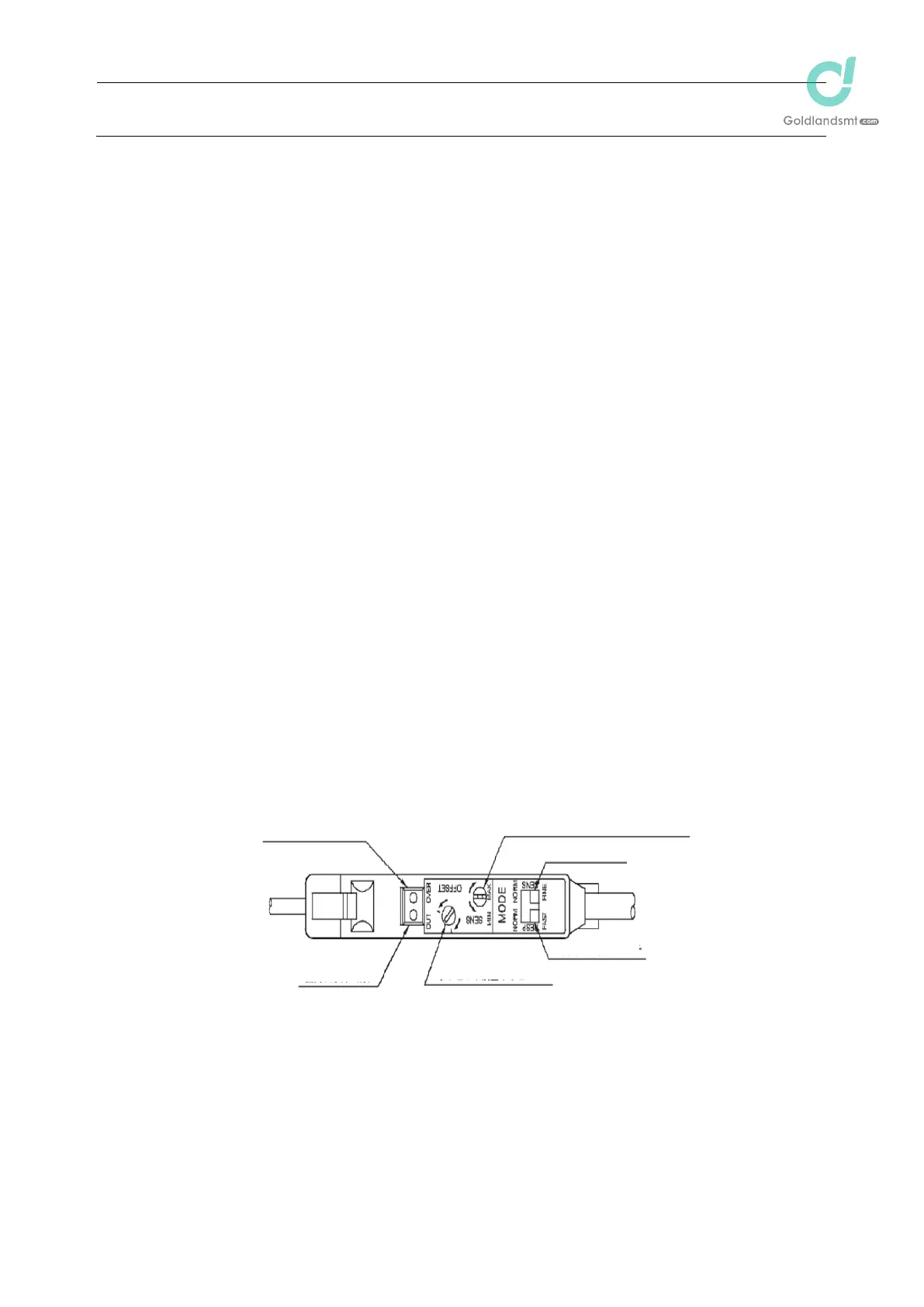
Output saturation
indicator (Red)
Output indicator
(Green)
Span adjustment (sensitivity adjustment)
controller (3 rotations)
Sensitivity change-over switch
Response time change-over switch
Offset adjustment controller

 Loading...


