– 22 –
3-10. Connecting the cords
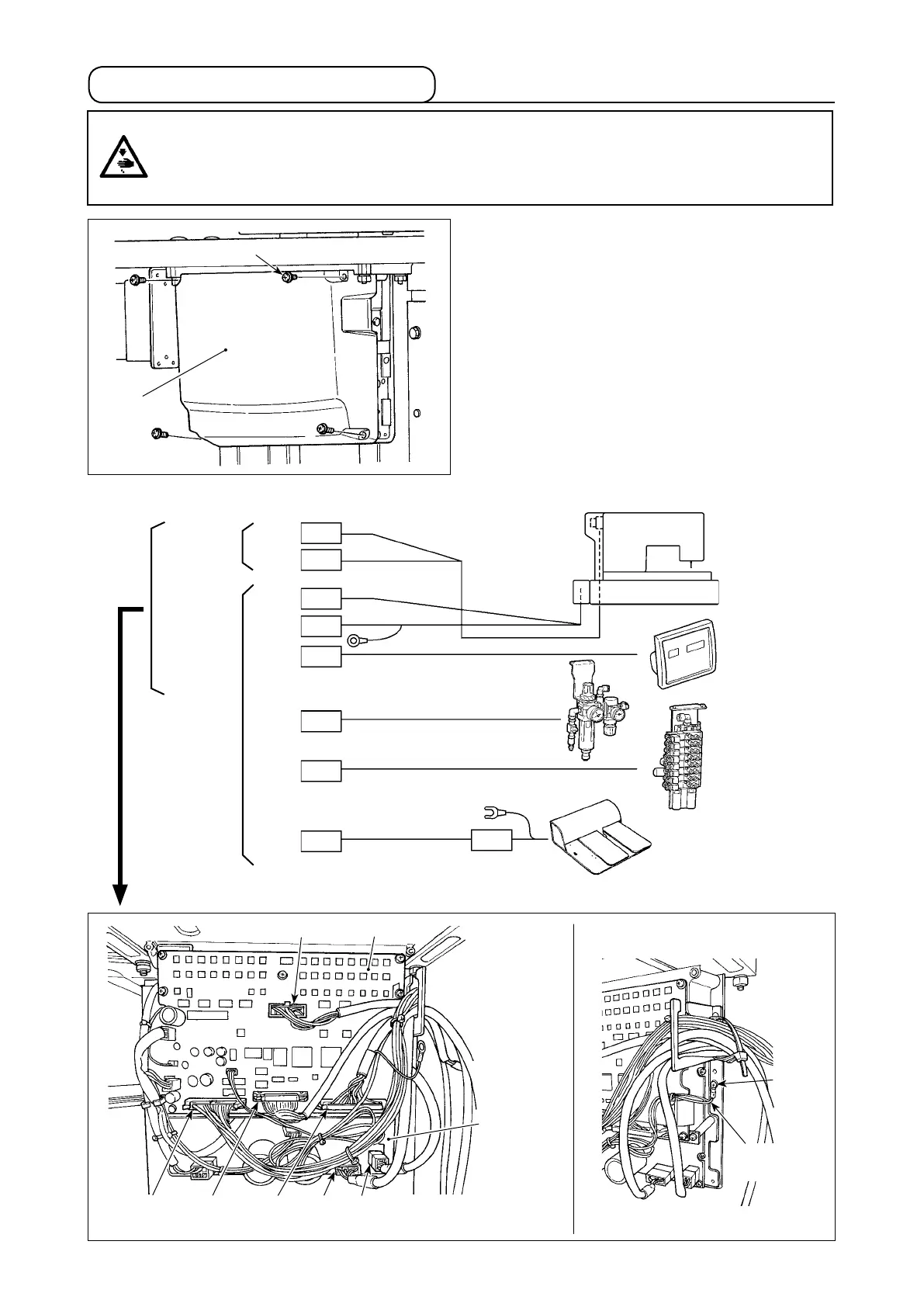
1) Loosen four setscrews ❷ of control box cover ❶.
Remove control box cover ❶.
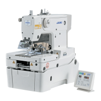
2) Connect the cords to the respective connectors
on MAIN PWB, SDC PWB. (Fig. 1)
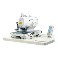
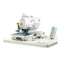
3) Fix the shielded ground wire of the INT PCB signal
cord at location A of the control box with a screw.
(Fig. 2)
SDC PWB
MAIN PWB
Sewing
machine head
Operation
panel
Foot pedal switch
(Option)
Air
switch
Solenoid
valve
CN34
26P
CN35
3P
CN44
30P
CN43 9P
10P
9P
CN15
CN17
4P
White
White
CN30
16P
CN45
50P
White
Brown
Gray
White
Blue
Red
DANGER :
To prevent personal injuries caused by electric shock hazards or abrupt start of the sewing
machine, carry out the work after turning OFF the power switch and a lapse of 5 minutes or more.
To prevent accidents caused by unaccustomed work or electric shock, request the electric expert
or engineer of our dealers when adjusting the electrical components.
MAIN PWB
SDC PWB
CN34
Gray
CN30 White
CN17
White
CN15
White
A
(Fig. 1)
(Fig. 2)
CN45
Brown
CN44
Blue
Shielded
ground wire
❶
❷