16
+ UzK
Ð UzK
U
V
W
M
3 ~
L (L1)
N (L2)
(L3)
+
Charge
*
PA
PB
}
L
N
PE
L
N
L3
L1
L2
PE
L1
L2
L3
OH
OH
Option
}
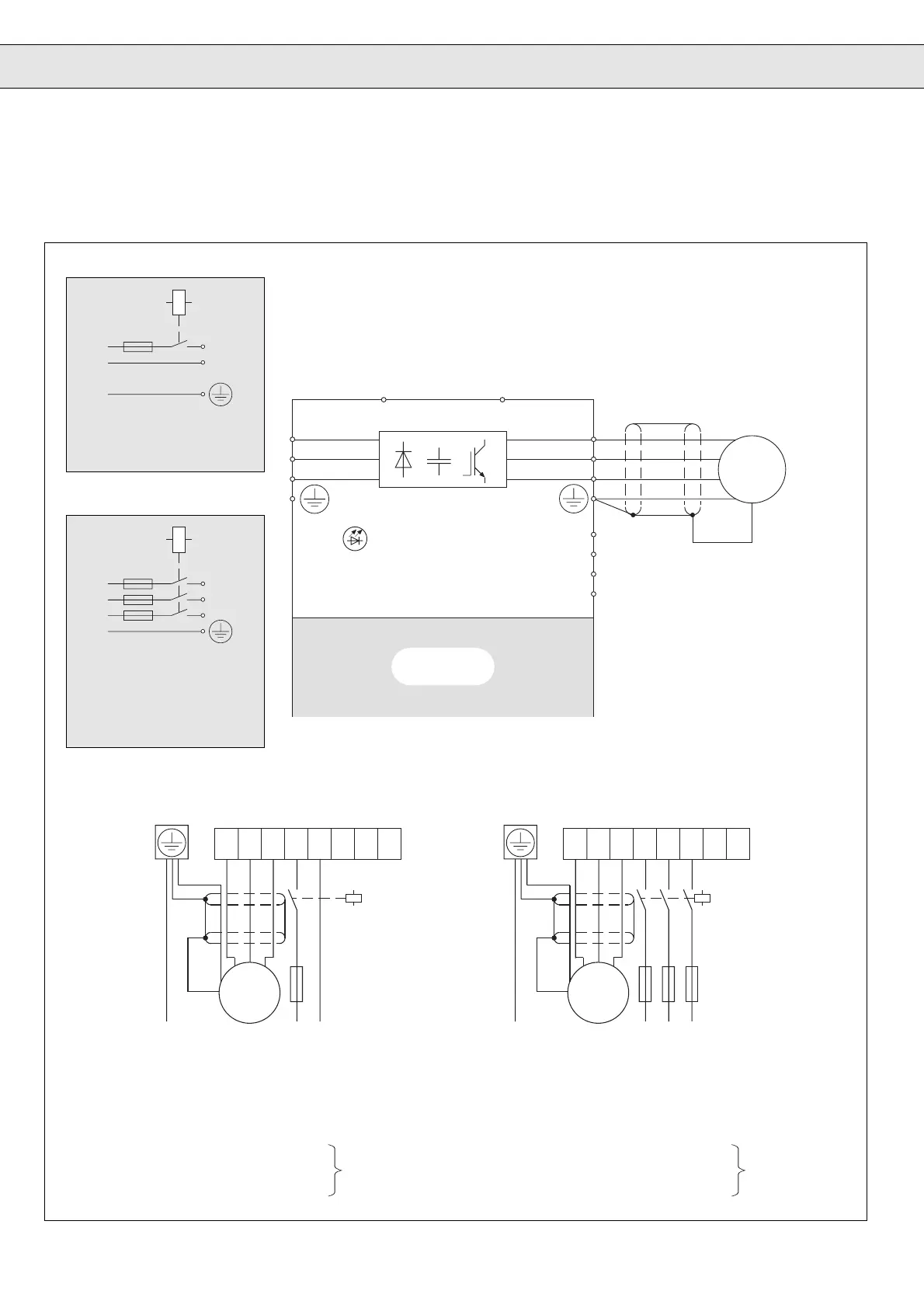
3. Connection
3.1 Wiring Diagram 200/400 V- Class Size 05…14
3. Anschluß
3.1 Anschlußplan 200/400 V-Klasse Größe 05…14
Standard nur bei Rackgeräten ab Größe 10!
Standard only for rack units from size 10
upwards!
3phasiger Anschluß
Größe 05…10 200V-Klasse (Option)
Größe 12 200V-Klasse (Standard)
Größe 09…14 400V-Klasse
3-phase connection
Size 05…10 200V Class (Option)
Size 12 200V Class (Standard)
Size 09…14 400V Class
1phasiger Anschluß
Nur Größe 05…10 200V-Klasse
1-phase connection
Only Size 05…10 200V Class
Steuerteil
Control Circuit
*) Schirm großflächig am Motorgehäuse an-
schließen!
Lay extensive shield on the motor housing!
UVW
-
UzK
+
UzK
(L3)(L1)
L
(L2)
N
L1 L2PE
M
3 ~
*
L3
UVW
-
UzK
+
UzK
(L3)(L1)
L
(L2)
N
LNPE
M
3 ~
*
*) Schirm großflächig am Motorgehäuse anschließen!
Lay extensive shield on the motor housing!
U, V, W Motor
PE Protective earth terminal
+UzK, -UzK DC voltage intermediate circuit
PA DC voltage intermediate circuit +
PB Braking transistor
OH, OH PTC-Evaluation (see page 103)
Connection brak-
ing components
see Chapter 9.1
Braking Module
U, V, W Motor
PE Schutzleiter
+UzK, -UzK Gleichspannung Zwischenkreis
PA Gleichspannungszwischenkreis +
PB Bremstransistor
OH, OH PTC-Auswertung (s.S. 103)
Anschluß Brems-
komponenten
siehe Kapitel 9.1
Bremsmodul
1phasiger Anschluß
1-phase connection
3phasiger Anschluß
3-phase connection
 Loading...


