17
ANTRIEBSTECHNIK
COMBIVERT F0
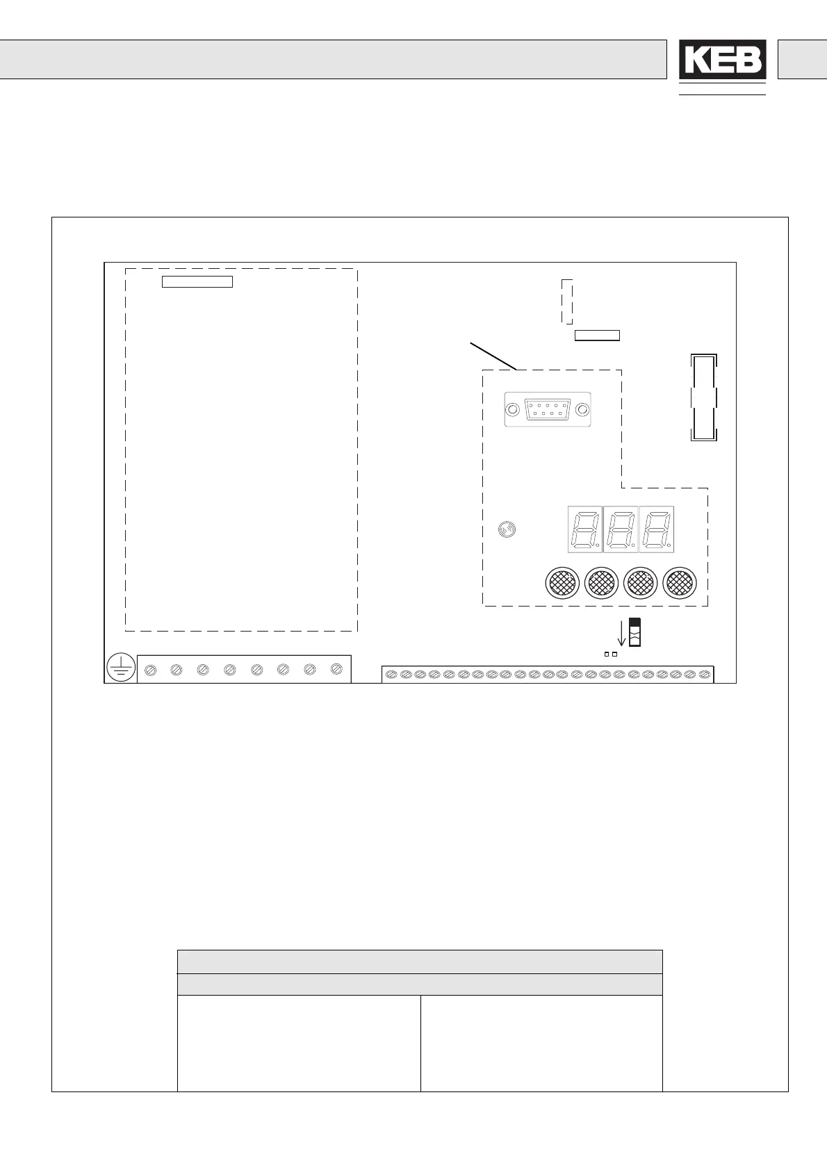
3.2 Steuer-/Treiber-/Leistungsteil
200/400 V-Klasse Größe 05…14
3.2 Control / Driver / Power Circuit
200/400 V Class Size 05…14
LD1 Charge LED
F1 Sicherung Zwischenkreis (siehe Tabelle)
F2 Sicherung Steuerteil 0,4 A träge
CN1 Options-/Diagnosestecker
SW1 Umschalter: Programmierbarer Relaisausgang Out1 (A)
Störsammelmeldung (B) (Werkseinstellung)
J1 Lötjumper für Stromeingang
X1 Klemmleiste Leistungsteil
X2 Klemmleiste Steuerteil
1) Serielle Schnittstelle Option Chassisgeräte
LD1 Charge LED
F1 Fuse Intermediate Circuit (see table)
F2 Fuse Control Circuit 0.4 A time-lag fuse
CN1 Option / Diagnosis Connector
SW1 Switch: Programmable Relay Output Out1 (A)
Collective Fault Message (B) (Factory setting)
J1 Solder Jumper for current input
X1 Terminal Strip Power Circuit
X2 Terminal Strip Control Circuit
1) Serial Interface Option Chassis Units
CN1
F2
F1
LD1
SW1
X1
1)
X2
J1
B
A
Leistungsteil
Power Circuit
Bei Rackausführung in der
Frontplatte.
At rack units located in the
front panel.
Sicherungen für Zwischenkreis / Fuses for Intermediate Circuit
Type F (flink / fast))
05 / 200 V 6,3 A 09 / 400 V 10 A
07 / 200 V 10 A 10 / 400 V 16 A
09 / 200 V 16 A 11 / 400 V 16 A
10 / 200 V 20 A 12 / 400 V 16 A
12 / 200 V 20 A 13 / 400 V 20 A
14 / 400 V 20 A
 Loading...


