GPIB Operation 7-3
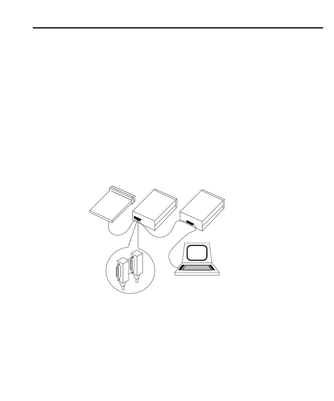
For a multi-unit test system, you can daisy-chain the instruments to the controller by
connecting an IEEE cable from one unit to another. Figure 7-2 shows a typical multi-unit
connecting scheme daisy chaining. Although any number of connectors could be stacked on one
instrume
nt's GPIB port, avoid possible mechanical damage by not stacking more than three.
Most controllers are equipped with an IEEE-488 style connector, but a few may require a
dif
ferent type of connecting cable. See the controller’s instruction manual if it is not equipped
with an IEEE-488 style connector.
CAUTION The IEEE-488 connector on the interface accepts metric screws. Do not use ear-
ly versions of IEEE-488 cables that do not use
metric screws to secure connec-
tions. On the GPIB cable connectors, metric screws are dark colored while non-
metric screws are
silver colored.
NOTE Daisy c
haining (Figure 7-2) is recommended when installing multi-unit connecting
schemes.
Figure 7-2
Daisy chaining
Instrument
Controller
Instrument Instrument
NOTE Observe the following limits concerning the IEEE-488 bus:
• There can be a maximum separation of 4 meters between any two instruments on the
bu
s.
• Make sure the maximum cable length used is the lesser of 20 meters or 2-meters mul-
tiplied by the number of devices.
• Limit the number of instruments on the bus to 15 (maximum) with no two instruments
having the sa
me address.
Test Equipment Depot - 800.517.8431 - 99 Washington Street Melrose, MA 02176
TestEquipmentDepot.com
 Loading...


