2-4 Return to Section Topics 6517B-900-01 Rev. A / Jun 2008
Section 2: Getting Started Model 6517B Electrometer User’s Manual
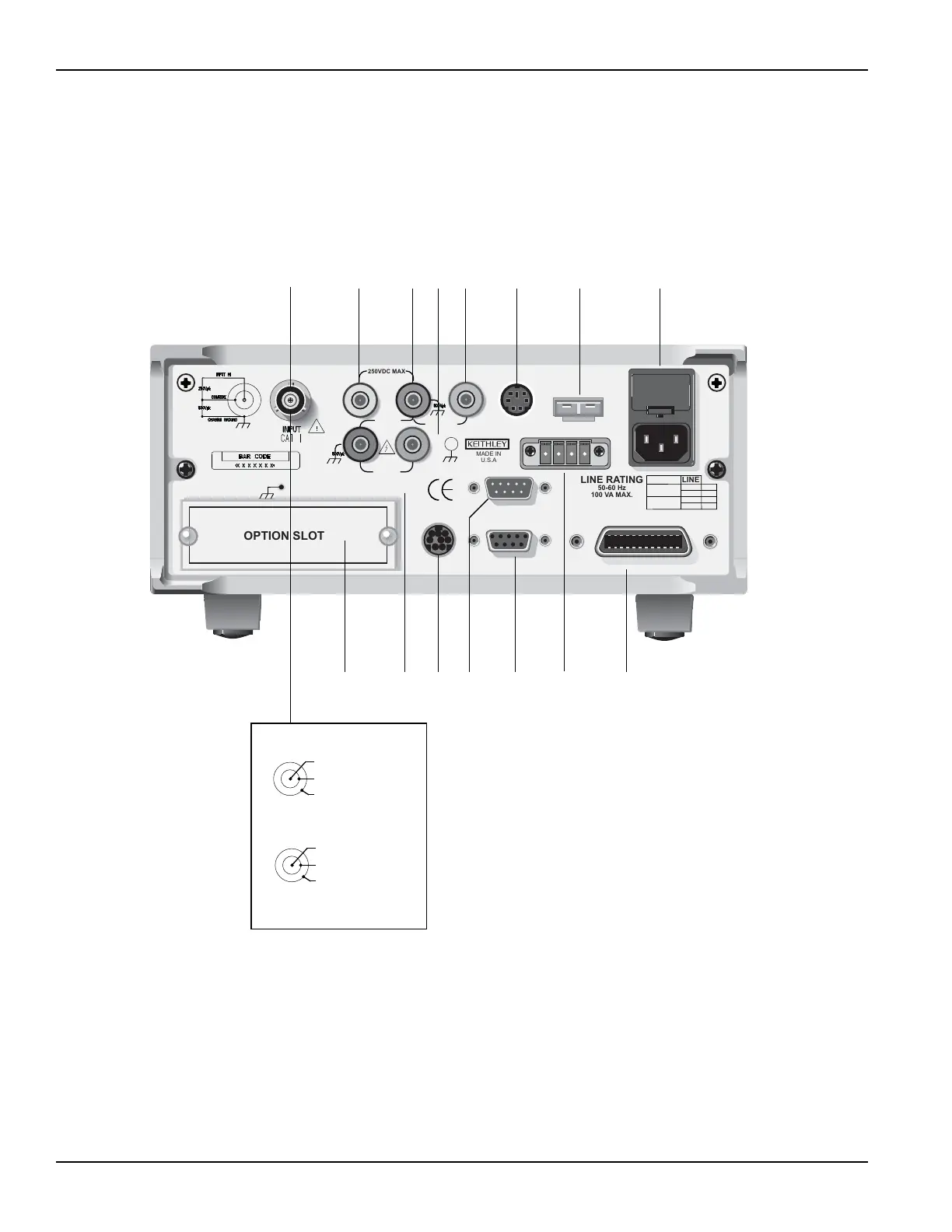
Rear panel summary
The rear panel of the Model 6517B is shown in Figure 2-2. The descriptions of the rear panel
components follow Figure 2-2.
Figure 2-2
Model 6517B rear panel
1 INPUT CONNECTOR
Unguarded Configuration Disable GUARD for amps, ohms, coulombs
and unguarded voltage measurements.
Guarded Configuration Enable GUARD for gua
rded voltage measurements.
2PREAMP OUT
Follows the signal amplitude applied to the INPUT terminal. With GUARD on, PREAMP OUT is connected
to the inner shell of the INPUT triax connector to configure the input for guarded voltage measurements.
Referenced to COMMON. See the Model 6517B Reference Manual for more information.
8
9101112131415
Input high
Input low
Chassis ground
Unguarded (guard off)
Input high
Guard
Chassis ground
Guarded (guard off)
OPTION SLOT
250VDC MAX
MADE IN
U.S.A
LINE RATING
50-60 Hz
100 VA MAX.
LINE
WARNING:
NO INTERNAL OPERATOR SERVICABLE PARTS, SERVICE BY QUALIFIED PERSONNEL ONLY.
CAUTION:
FOR CONTINUED PROTECTION AGAINST FIRE HAZARD, REPLACE FUSE WITH SAME TYPE AND RATING.
1250Vpk
PREAMP
OUT
1000VDC
MAX
FUSE
630mAT
315mAT
100V
120V
220V
240V
COMMON 2V OUT
LO HI
V SOURCE
TRIGGER LINK RS-232
DIGITAL I/O
HUMIDITY
TEMP
TYPE K
INTERLOCK
IEEE-488
2VDC MAX
1234567
Test Equipment Depot - 800.517.8431 - 99 Washington Street Melrose, MA 02176
TestEquipmentDepot.com

 Loading...


