4-6 Return to Section Topics 6517B-900-01 Rev. A / Jun 2008
Section 4: Measurement Options Model 6517B Electrometer User’s Manual
Navigating menus
Use the following rules to navigate through the menu structures. Table 4-5 summarizes the front
panel keys used for navigation.
1. From the instrument’s normal state of
displaying readings, you can:
• View a configuration menu by pressing CONFIG and then the desired function or
operation key.
• View the top level of the main menu by pressing the MENU key.
2. The unit is returned to the normal reading display by:
•Pressing EXIT or MENU from the top level of the main menu.
•Pressing EXIT from the top level of a configuration menu.
• Pressing a measurement function key from within a menu.
3. Pressing the ENTER key selects an item and, if further definition is needed, moves down
within the menu structure. Pressing the EXIT key backs up within a menu structure.
4. The cursor position is denoted by a blinking menu item or parameter. The cursor is moved
from one item to the next using the cursor keys ( and
). To select an item, highlight it with
the cursor, then press ENTER.
5. A displayed arrow ( or ) on the bottom line indicates there is more information or
additional menu items to select from. When is displayed, use the cursor key. The cursor
keys have an auto-repeat feature.
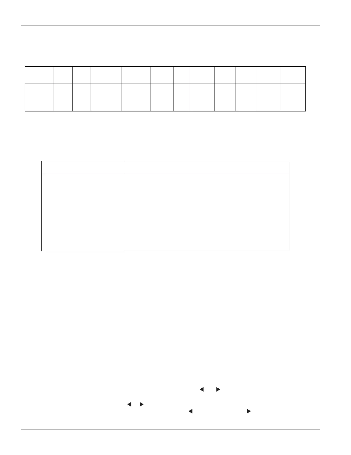
Table 4-3
Configuration settings for each measurement function
Function Speed Filter Resolution
Autorange
limit
s Damping Guard
External
feedback
Amps
rel
Meas
type*
V-
Source**
Auto
discharge
Volts
Amps
Ohms
Coulombs
•
•
•
•
•
•
•
•
•
•
•
•
•
•
•
•
•
•
••
•• •
•
**Resistance or resistivity
**Auto or manual
Table 4-4
Configuration settings for instrument operations
Option Description
CONFIG REL
CONFIG FILTER
CONFIG MATH
CONFIG TRIG
CONFIG SEQ
CONFIG STORE
CONFIG VOLTAGE SOURCE*
CONFIG CARD
CONFIG NEXT
CONFIG Z-CHK
Set rel (relative) value and enable.
Select and configure averaging, and median filters.
Select and configure math calculation: polynomial, percent, percent
deviation, ratio or log10.
Select and configure basic or advanced trigger model.
Select and configure test sequence.
Configure data store: set count, control, timestamp, elements and
display, and clear buffer.
Configure V-Source: range, V-limit, resistive I-limit, and meter connect.
Select and configure internal or external scanning.
Change the scale for the zero-center bar graph.
Set whether readings are shown in Zero-Check mode.
*To access the V-Source menu, press CONFIG and then any one of the VOLTAGE SOURCE keys.
Test Equipment Depot - 800.517.8431 - 99 Washington Street Melrose, MA 02176
TestEquipmentDepot.com

 Loading...


