6517B-900-01 Rev. A / Jun 2008 Return to Section Topics 4-23
Model 6517B Electrometer User’s Manual Section 4: Measurement Options
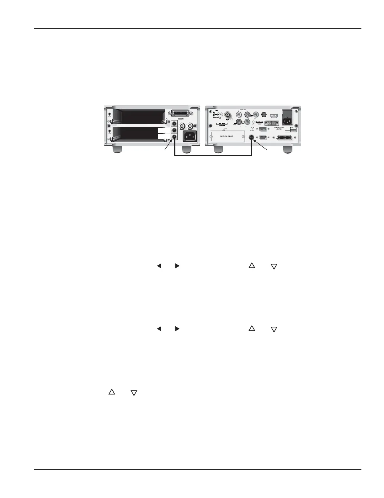
Trigger connections
Connect the Model 6517B to the switch system as shown in Figure 4-9. Detailed information on
triggers is provided in Section 7 of the Reference Manual.
Figure 4-9
Trigger connections using trigger link
Configure external channels
The scanner configuration menu is used to specify the number of channels (external inputs) for the
scan. If a scanner card is installed in the option slot of the Model 6517B, use procedure A. If the
option slot is empty, use procedure B.
Procedure A
Scanner installed in option slot of Model 6517B:
1. Press CONFIG an
d then CARD to display the scanner configuration menu.
2. Place the cursor on EXTERNAL and press ENTER.
3. You will then be prompted to enter the number of external inputs (channels) for the scan.
Use cursor keys
( and ) and the RANGE keys ( and ) to change the number (1 to
400). Press ENTER to continue.
4. Press EXIT to return to the normal measurement display.
Procedure B
Option slot of Model 6517B empty:
1. Press CONFIG an
d then CARD to display the scanner configuration menu.
2. You will then be prompted to enter the number of external inputs (channels) for the scan.
Use cursor keys
( and ) and the RANGE keys ( and ) to change the number (1 to
400).
3. Press ENTER to return to the normal measurement display.
Perform the scan
Perform the following steps to scan external channels. Note that menu items are selected by
placing the cursor on it and pressing ENTER. A parameter value is changed by using the RANGE
keys (
and ). and pressing ENTER.
1. On the Model 6517B, press the C
ARD key. If a scanner card is installed in the option slot of
the Model 6517B, perform steps a and b. If the option slot is empty, proceed to step 2.
a. Place the cursor on PERFORM-SCAN and press ENTER to display the scan types
(internal or external).
b. Place the cursor on EXTERNAL and press ENTER.
2. On the Switch System, if not already done, reset the Model 7001/2 as follows:
a. Press MENU.
WARNING:
NO INTERNAL OPERATOR SERVICABLE PARTS,SERVICE BY QUALIFIED PERSONNEL ONLY.
CAUTION:
FOR CONTINUED PROTECTION AGAINST FIRE HAZARD,REPLACE FUSE WITH SAME TYPE AND RATI
MADE IN USA
Model 7001 or 7002 Switch System
6517B Electrometer
OUT
IN
Trigger
Link
Trigger Link Cable (8501)
OPTION SLOT
250VDC MAX
MADE IN
U.S.A
LINE RATING
50-60 Hz
100 VA MAX.
LINE
WARNING:
NO INTERNAL OPERATOR SERVICABLE PARTS, SERVICE BY QUALIFIED PERSONNEL ONLY.
CAUTION:
FOR CONTINUED PROTECTION AGAINST FIRE HAZARD, REPLACE FUSE WITH SAME TYPE AND RATING.
1250Vpk
PREAMP
OUT
1000VDC
MAX
FUSE
630mAT
315mAT
100V
120V
220V
240V
COMMON 2V OUT
LO HI
V SOURCE
TRIGGER LINK RS-232
DIGITAL I/O
HUMIDITY
TEMP
TYPE K
INTERLOCK
IEEE-488
2VDC MAX
Trigger
Link
Test Equipment Depot - 800.517.8431 - 99 Washington Street Melrose, MA 02176
TestEquipmentDepot.com

 Loading...


