2-6 Return to Section Topics 6517B-900-01 Rev. A / Jun 2008
Section 2: Getting Started Model 6517B Electrometer User’s Manual
Power-up
Line power connection
Follow the procedure below to connect the Model 6517B to line power and turn on the instrument.
CAUTION Operating the instrument on an incorrect line voltage may cause damage to
t
he instrument, possibly voiding the warranty.
1. Before plugging in the power cord, make sure that th
e front panel power switch is in the off
(O) position. Be sure that line input voltage is set to the correct range for the power supply
being used to power the Model 6517B.
NOTE L
ine voltage is pre-set at the factory, but may be reset in the field by adjusting the voltage
selector behind the left ear. To access the voltage selector, first remove the handle then
remove the left mounting ear. The current voltage setting is the marking closest to the
small circle.
2. Connect the female end of the supplied power cord to the AC receptacle on the rear panel.
Con
nect the other end of the power cord to a grounded AC outlet.
WARNING The power cord supplied with the Model 6517B contains a separate ground
wire for use with grounded outlets. When proper connections are made,
instrument chassis is connected to power line ground through the ground
wire in the power cord. Failure to use a grounded outlet may result in personal
injury or death due to electric shock.
Power-up procedure
1. Turn on the instrument by pressing the front panel power switch to the on (I) position.
2. During power-up, the Model 6517B performs self-tests on its memory elements. If a failure
occurs, the instrument momentarily displays an error message and turns on the ERR
annunciator. If the instrument passes the self-tests, the firmware revision level and bus
interface information are displayed. For complete information on the power-up sequence,
see Section 2 in the Model 6517B Reference Manual.
Display
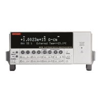
As shown in the Model 6517B front panel illustration (see Figure 2-1), the front panel has three
lines of display information: the primary display line, the secondary display line, and annunciators.
Primary display line
The top line displays readings along with units. It can also display measurement type, “hold,” math
operating type, channel number, menu headings, and messages. Status and error messages are
listed in Section 2 of the Reference Manual.
Test Equipment Depot - 800.517.8431 - 99 Washington Street Melrose, MA 02176
TestEquipmentDepot.com

 Loading...